Different projects
The purpose of this site is to describe some of my both big or small projects, where I tried to improve different products, build my own gadgets or solve annoying everyday problems.
LIST of CONTENTS:
- • My DPH3205 power supply
- - DPH3205 in a box
- • The most advanced Li-ion battery pack I ever bult
- - Battery Cells & BMS
- - DPH5005 Power Sypply
- - MOT Microwave Owen Transformer
- - kWeld, Battery Spot Welder
- - The Battery Package
- - The Battery Enclosure
- - Android & iOS Apps
- • Black&Decker Dustbuster Flexi, battery replacement
- • Temperature Calibrator
- • My own design for 3D printing
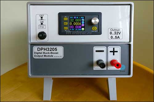
My DPH3205 power supply
Updated: June 19, 2022.
Power Supply, photo album of this project.
As a frequent Ebay and
Banggood buyer it was hard not to
notice advertisement for the interesting products of the Chinese
company RD® i.e. Ruideng Technologies from Hongzhou.
There are several digital programmable power converters: several buck, and one buck & boost
converter with keyboard and display interface. I perform some Google search to see if it is something to have.
Do these gadgets have enough quality? Are they enough accurate?
I stumbled on an interesting Danish site Lygte-info.
This guy has spent lot of time testing different products. I was lucky to find here a
very detailed test and review of the
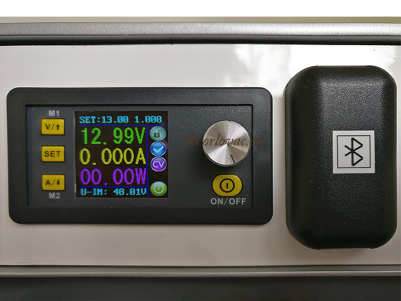
DPH3205 module.
 This digital programmable
power buck & boost module seems to be most interesting for me, because it is most versatile. It allows you to have
fixed or variable DC input power source and to get variable regulated output from
0..32V and
0..5A with low heat dissipation.
Or if you have DC input source with enough power, in already mentioned voltage range,
it may be suitable as input power to this module to get whole output voltage range.
Output voltage och current is obtained by help of rotary encoder knob or by calling previously programmed values from the unit memory.
This digital programmable
power buck & boost module seems to be most interesting for me, because it is most versatile. It allows you to have
fixed or variable DC input power source and to get variable regulated output from
0..32V and
0..5A with low heat dissipation.
Or if you have DC input source with enough power, in already mentioned voltage range,
it may be suitable as input power to this module to get whole output voltage range.
Output voltage och current is obtained by help of rotary encoder knob or by calling previously programmed values from the unit memory.
After reading this detailed review,
I was convinced that it is right thing for me. A DPH3205 for € 25 is irresistible interesting. I couldn't wait and made a purchase at Banggood.
After less than 4 weeks arrived my package with well protected content.
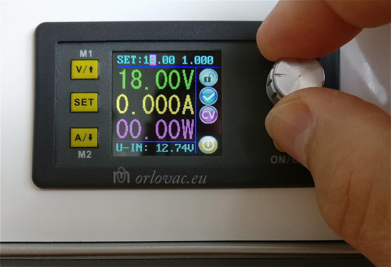
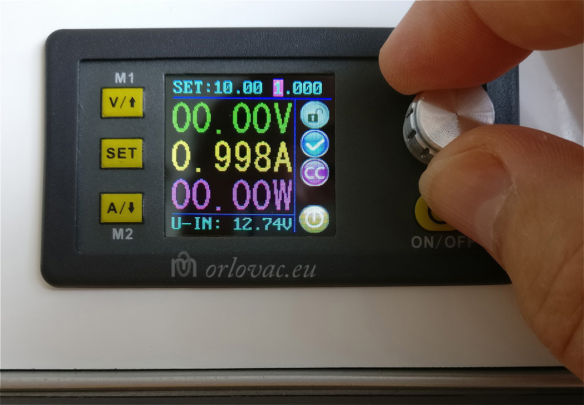
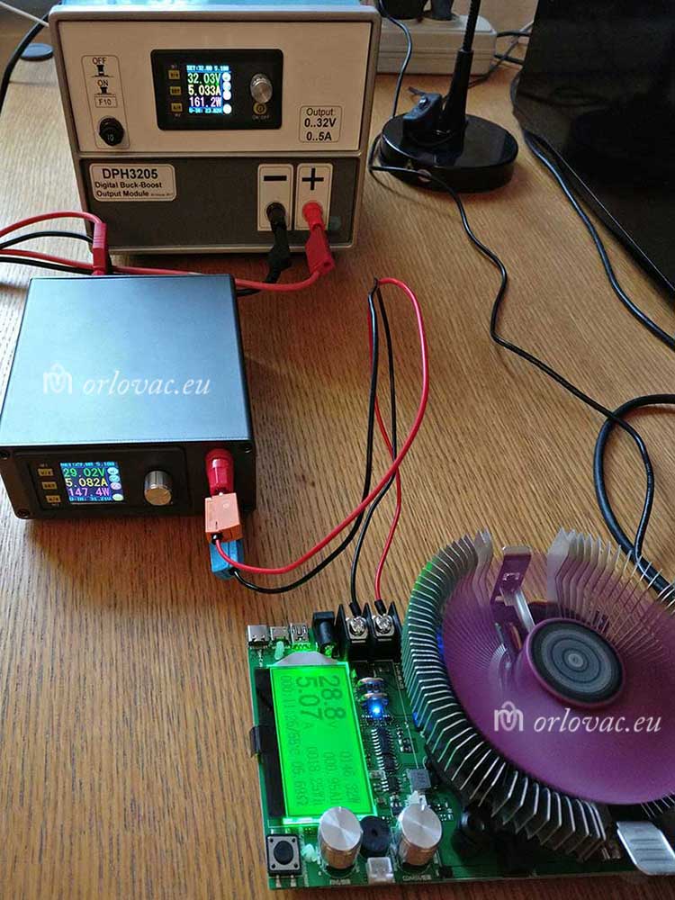
I immediately started my own testing of this module just to learn how to use and to be acquainted with it. Of course,
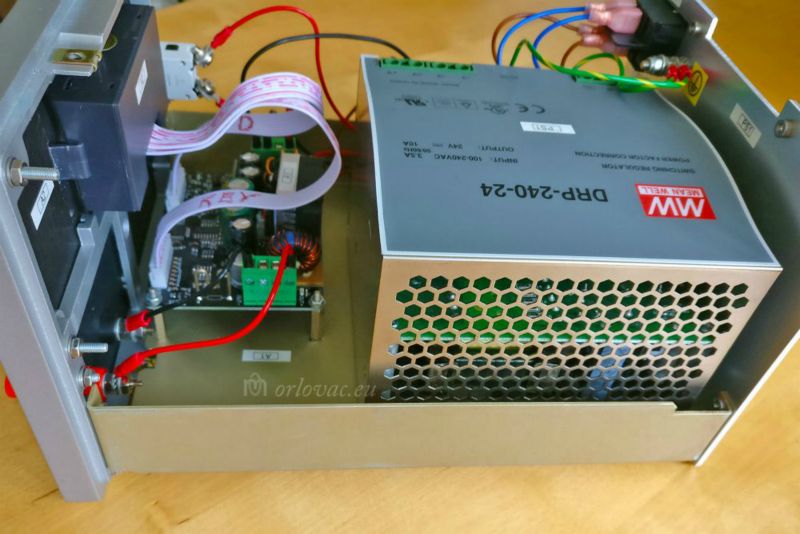
I fell in love with it. I have realized how good and practical it would be if I made my own Power Supply with it. I checked my stock and find an
SMPS Mean Well DRP-240-24,
i.e. 24V/10A for the primary power source and tested them together. I was again surprised by performance of this module.
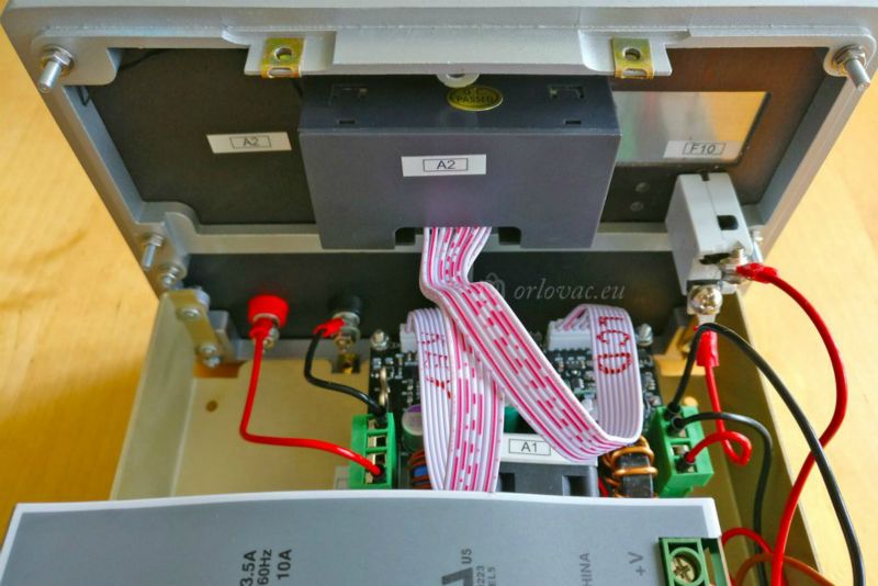
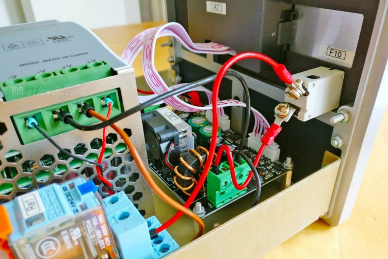
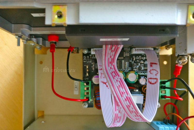
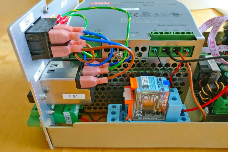
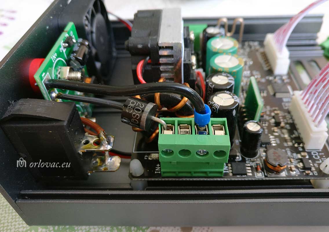
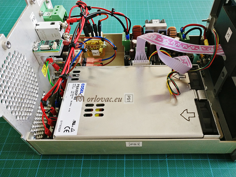
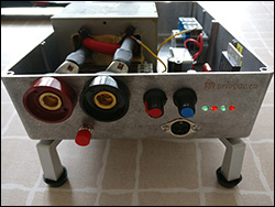
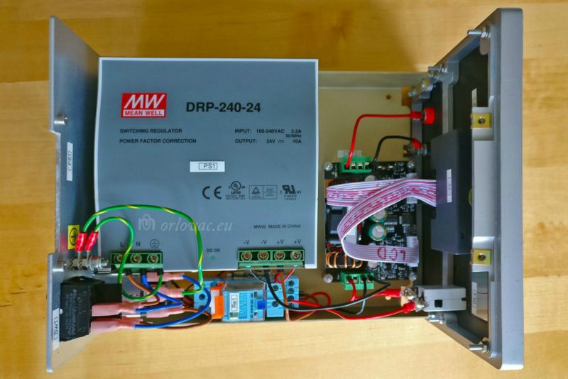 Power Supply, open, top view.
Mechanical construction:
I knew that most complex problem could be to find some appropriate enclosure. This used to be expensive and cost much more then the module itself.
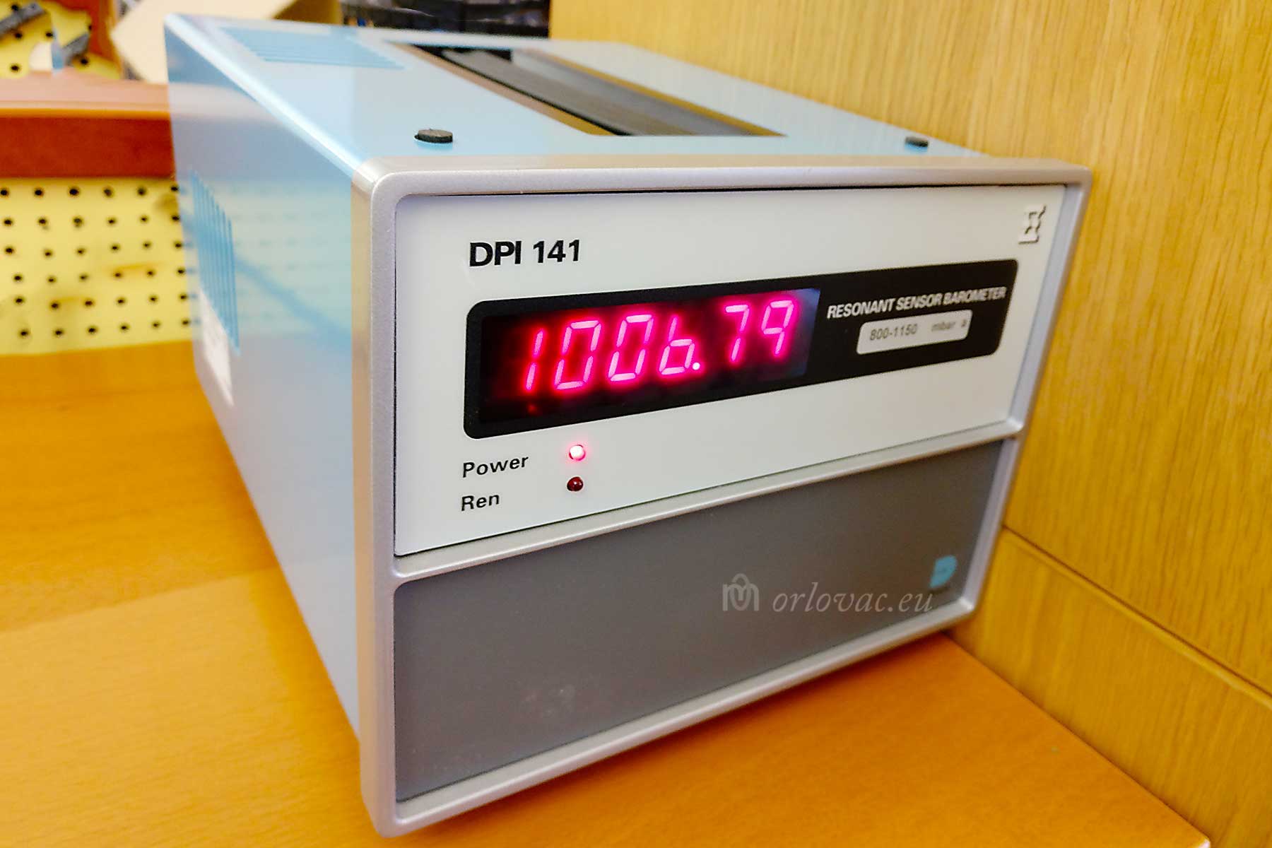
For many years on a shelf, in front of my eyes, I had a analogue barometer unit
DPI 141,
which just shows current Air pressure. It was discontinued and not
used anymore in our products. DPI 141
has a perfect enclosure
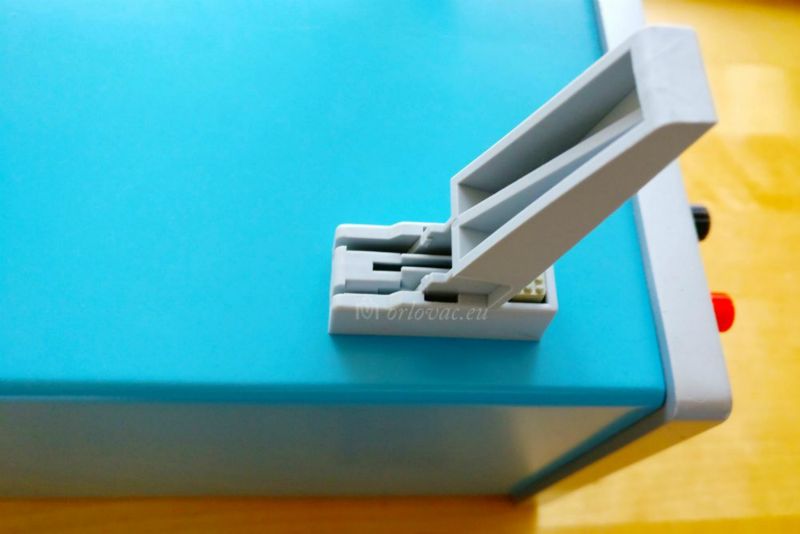
for this project: dimensions exactly as needed, two nice front panels and very useful
flip-up front feet.
I could not find anything better. At first, I thought it would be nice if it is possible to fit two of DPH3205 modules in it
to get Power Supply with dual output. The box was not big enough for this purpose. Though it was excellent for a complete single regulated Power Supply and
I made decision to build my own programmable Laboratory Power Supply!
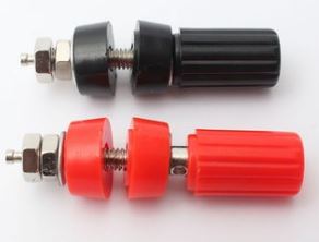
I needed to make a minor purchase of a pair of 4 mm
screw terminal post with a
radial
hole through it for an easier output wire or banana connection and access.
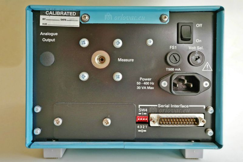
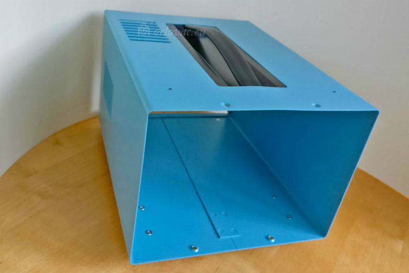
Additional € 2 and about four weeks of waiting (I had lot of these without a radial hole). During that time I opened the barometer unit,
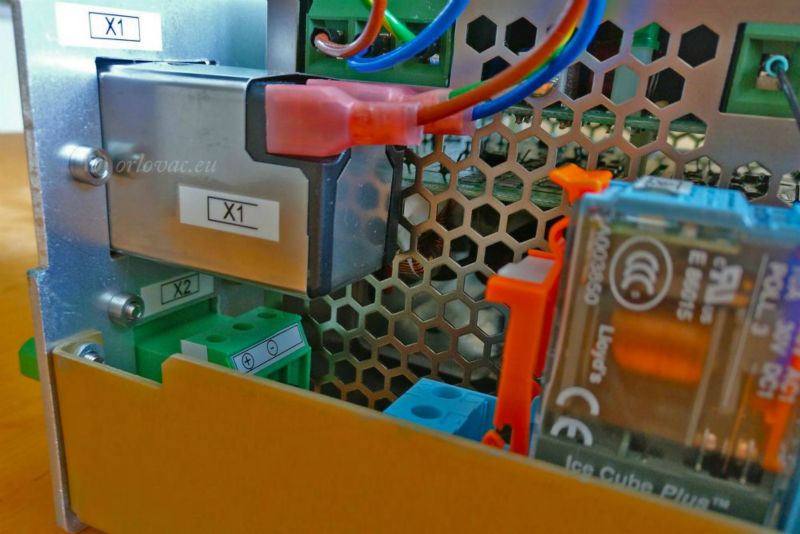
removed all content, prepared front panels and made a completely new rear panel from a Schroff aluminum panel plate of 2.5 mm thickness. I cut out
all holes I needed (for Mains switch Sw1,
connectors X1
and X2)
on the rear panel.
 On the upper front panel I removed original front sticker and replaced it with thin
(1mm) aluminum plate with one surface in white turned outside. Two holes are needed here: one for the
Display unit A2 and a hole for the
F10
fuse and circuit breaker.
On the upper front panel I removed original front sticker and replaced it with thin
(1mm) aluminum plate with one surface in white turned outside. Two holes are needed here: one for the
Display unit A2 and a hole for the
F10
fuse and circuit breaker.
Lower front panel I kept unchanged, except the two identical holes for "banana" 4 mm screw terminals (red and black).
The inner in-between holder plate was perfect as it was and needed only some holes to be drilled: 4 holes for digital power module
A1, 3 holes for the
primary power supply PS1
and finally two holes for the 35 mm DIN rail which will keep
Re1 Relay socket.
MECHANICAL DRAWINGS
I won't present any mechanical drawings. The reason is that I did not use a commercial enclosure.
The chance that you have the same box is very little. I spent little more time trying to
make good photographs which are presented here in the
photo album. You have to make your own adaptation for obtained enclosure.
Dimensions of my enclosure are:
- width = 190mm
- height = 140mm
- depth = 250mm
Schematic diagram of this Power Supply
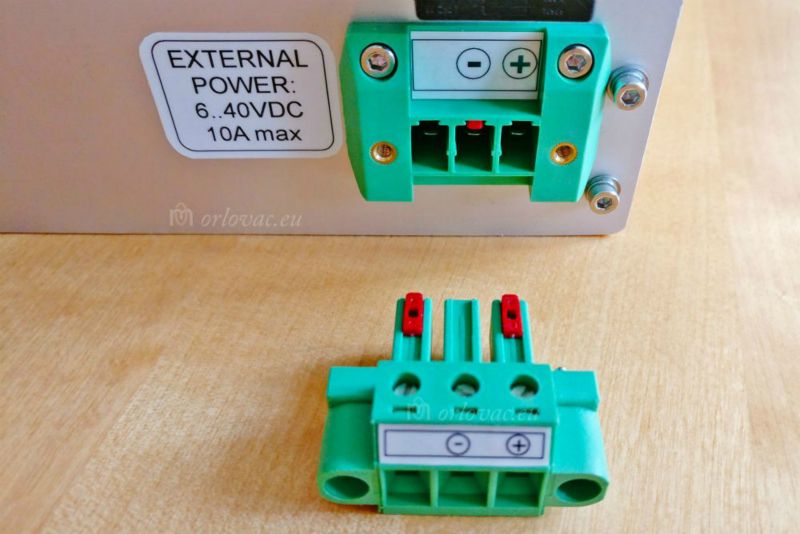
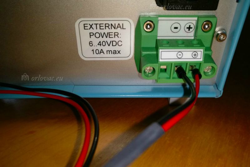
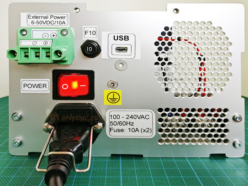
During this work I developed an idea: if I made possibility to connect external power source (6..40VDC) too, then it would be possible to power this PS, for example: from my car battery, solar power panel or any other DC source (in required voltage range). It would be very practical and add more value to this project.
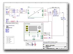
By help of OrCAD I drew the schematic diagram for my Power Supply.
I did not like to manually switch between these power input sources (X1
or X2) but want it to work automatically.
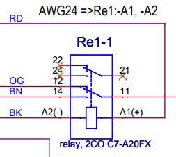
For this purpose Re1 is used.
Re1 works in this way:
1) When digital output power module A1 is supplied from electrical grid through
X1,
PS1 will activate
Re1 and +24V output from
PS1 is fed to the
Re1:14. As the relay is in activated state,
Re1:14 is connected to the
Re1:11 terminal and then it goes to the
F10 (airplane) fuse circuit breaker and finally
continues to the Digital Programmable Output Power Module
A1:In+ terminal.
2) If there is no Mains power, but external DC power source does exist, input power is fed through
X2 (Phoenix) 20A terminal connector.
Re1 is not activated in this case.
The positive pole of the external voltage source is connected to the
Re1:12 terminal and goes through the inactivated relay to the
Re1:11 connection terminal, continues
via
F10 to the Digital Output Power Module
A1:In+ terminal.
In this case we may have any input voltage between 6..40VDC and it needn't to be stabile. The output module
A2 will function properly.
For full output power, input voltage must be higher than 18VDC and has minimum of 180W of power.
3) This design may have redundant input power supply. If input power is presented on both
X1
(DC) and X2 (AC) connectors.
Mains power will feed output module (described above under point 1.). If, of some reason, mains power disappears, this Power Supply
will automatically turn to DC source from connector
X2,
almost without any interrupt. This is not an usual feature in an ordinary Power Supply.
Minus pole (GND) from both sources are connected directly to A1:In- terminal.
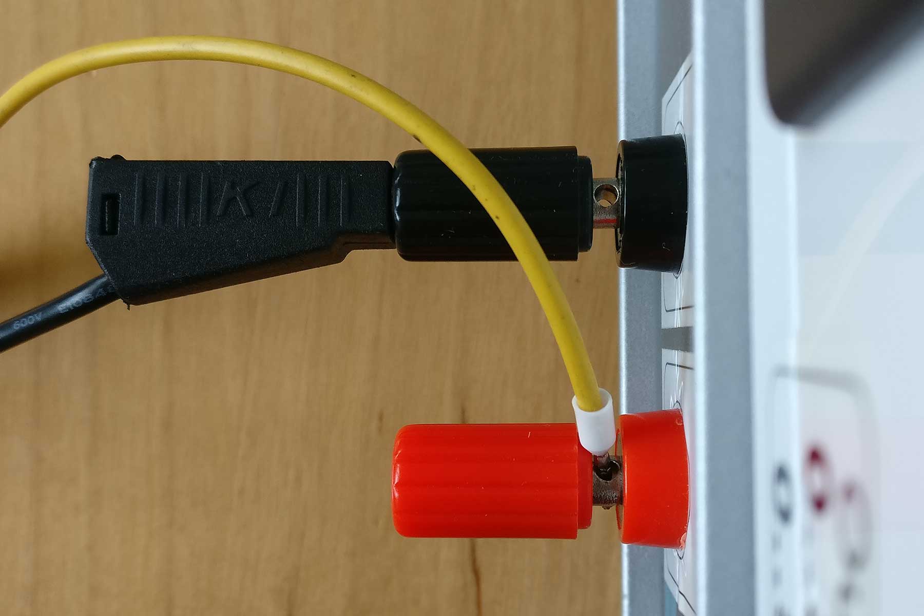
At any time you can switch off power to the output module A1 by pulling out the knob of F10 fuse (circuit breaker). When F10 is pulled out or tripped off automatically when over current is presented a white ring is exposed on the knob's body. It is shown on the F10's label too. This is a fuse and breaker at the same time.
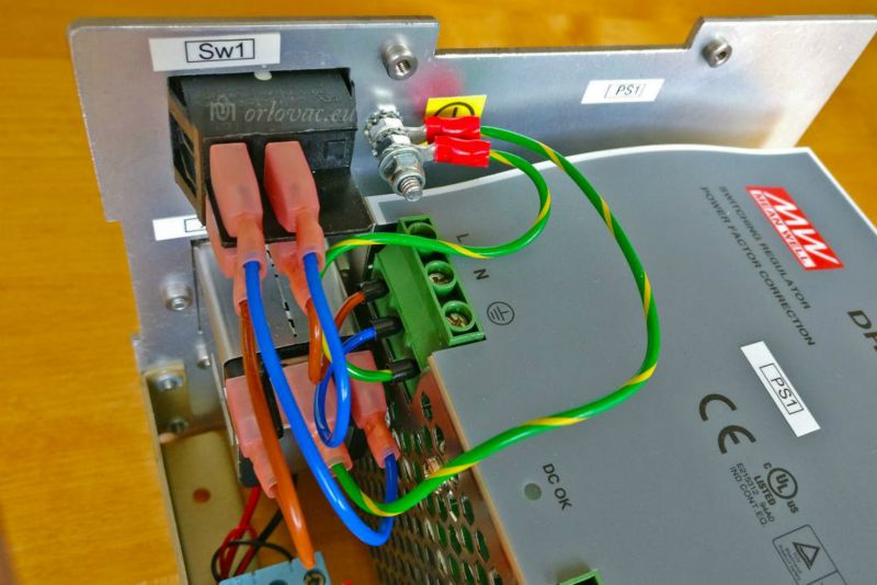
I used three different wire gauges in this project:
1) AWG20 (0.5mm2) for mains part of the Power Supply. Blue (BU) for Neutral (N), brown (BN) for Line (L1) and
yellow-green for Protective Earth (PE).
2) AWG24 (0.25mm2) for mating of Re1: A1(+), A2(-). Black (BK) minus relay polarity (A2) and red (RD) for plus relay polarity (A1).
3) AWG16 (1.5mm2) is used for the rest of connections. Black (BK) for minus polarity, GND. Red (RD) for plus polarity.
Orange (OG) plus polarity X1 - Re1; brown (BN) between Re1 - F10 - A1.
Do not be fooled by thickness of used wires! I have used teflon i.e. PTFE (polytetrafluoreten) insulated wire. PTFE is much more thinner and temperature resistant than ordinary PVC insulation. These wires are approved for 13.5A/mm2 if the wire is laid free (which is the case here).
Bill of materials (BOM):
Beside the DPH3205 module, you need:
| D. | Part no. | Qty | Description of the part | Manuf. |
| A1, A2 | DPH3205 | 1 | Digital programmable buck&boost module | Ruideng |
| PS1 | DRP-240-24 | 1 | SMPS 24V/10A 240VA | MeanWell |
| X1 | FN9260 | 1 | Power entri 10A with 3.15A (x2) | Schaffner |
| F1, F2 | 02183.15HXP | 2 | 5x20mm 3.15A fuse | Littelfuse |
| X2 | 1840560 | 1 | 20A power connector (terminal) DFK-PC 4/3-GF-7,62 | Phoenix |
| Re1 | C7-A20FX | 1 | Relay with its socket 24V/10A | Releco |
| F10 | 483-G411-K1M1-A1S0Z-10A | 1 | 10A fuse and circuit breaker | ETA |
| Sw1 | C6053ALBR3-1197W-B | 1 | DPST panel rocker switch 250V/20A | Bulgin |
| D1 | 20SQ045 | 1 | 20SQ045 20A 45V Schottky Diode | Liteon |
| +, - | 965386 | 1 pair | 4mm banana screw socket, red & black | on Banggood |
| - | 1-966067-2 | 12 | End sleve Black (AWG16) | TE-connectivity |
| - | 966067-2 | 7 | End sleve White (AWG20) | TE-connectivity |
| - | 2-520184-4 | 7 | Faston receptacle 6.3mm red | TE-connectivity |
| - | 34148 | 6 | Ring terminal 4,3mm, red | TE-connectivity |
| - | 24291 | 4 | M3x15mm standoff | Keystone |
| - | 35mm DIN rail | 50mm | 35mm DIN rail | Any |
Add some M3: nut, washer and screws of different length to fit all necessary details. Some label printer would be nice to have for example: Dymo 2000 or some of Brother brand.
Digital Programmable Power Module DPH3205 specifications:
According to Ruideng's Operating instructions:
- Input voltage range: 6 - 40VDC
- Output voltage range: 0V - 32.00V
- Output current: 0A - 5.00A
- Max. aloud input current: 10A
- Output ripple: about 100mVpp
- Output voltage resolution: 0.01V
- Output current resolution: 0.001A
- Environment temperature range: -10°C...+45°C
- For full output load, input source must be higher than 18V and dispose of 180W.
- Operation: CV,
CC
My Power Supply specifications:
Everything what is sad for DPH3205 module is the same for my power supply.
- Dual input power source: internal 24VDC and external 6..40VDC
- Input power redundancy
- Automatic operation on available input power source
- Dimensions: W190mm, H140mm, D250mm
- Easy external power connection (connector + connection terminal)
- Convenient reading angle and access when front feet are pulled-out
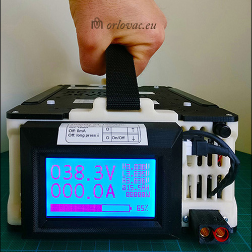
- practical recessed currying handle
Improvement:
Viktor Orlovac has suggested to add a Schottky diode between connector X2:1 and Re1:12 to protect DPH3205 converter from accidental reverse voltage when the Power Supply is mated from external power source. I used 20A 45V Liteon diode type 20SQ045 and it works fine now without almost any dissipation with full load.
DPH3205 IN A BOX
In a case you do not have an appropriate box for this module, manufacturer Ruideng
(Hangzhou Ruideng Technolologies Co. Ltd) has made a housing box for this module.
On Aliexpress and Ruideng official store, you can find DPH3205
housing box
(link provided here is on the day of writing). Remember to choose: Choice2-A, price about EUR 20.
 When you order and get both details: DPH3205 module and its housing, you have only to assemble it.
In this case, you have to have primary power source outside of the box. If you use it (for example) in you vehicle, power source
is external anyway (12VDC or 24VDC).
When you order and get both details: DPH3205 module and its housing, you have only to assemble it.
In this case, you have to have primary power source outside of the box. If you use it (for example) in you vehicle, power source
is external anyway (12VDC or 24VDC).
I have made some improvement: added a Schottky diode to protect input from reversal voltage (described above in the text); A Thermal Protector KSD9700 of 40°C with normally open (NO) contacts. It can be mounted on the DPH3205 heatsink. This improvement will save the built in fan and you ears from boring fan's sound. Otherwise, the fan will always run when module is powered. Adding a thermostat of 40°C (NO), will only activate the fan when thermostat's temperature exceeds that value.
BOM for converter in a box
| Part no. | Qty | Description of the part | Manuf. |
| Housing box Choice2-A | 1 | Housing box, Choice2-A for DPH3205 module | Ruideng |
| 20SQ045 | 1 | 20SQ045 20A 45V Schottky Diode | Liteon |
| KDS9700 | 1 | KSD-9700 40°C (NO) Thermal Protector | Shenzen Boyechuangzhan Electronics Co.,Ltd |
| 34148 | 2 | Ring terminal 4,3mm, red | TE-connectivity |
| 1-966067-2 | 4 | End sleve Black (AWG16) | TE-connectivity |
If you have some comment or suggestions, feel free to e-mail me.
Designed by: Marinko Orlovac, 2017.
Reviewed by: Tony Sunnarborg.
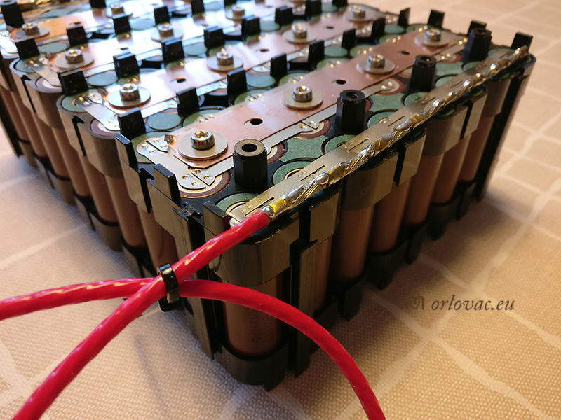
The most advanced Li-ion battery pack I ever built
Updated: February 24, 2020.
Lithium-ion Safety Concerns:
If you do not know what your are doing or you do not have any experience
about these batteries, do not play with them. They can store lot of energy, which can hurt you seriously
and you can burn down your home. I have warned you and I won't be responsible for what you are doing.
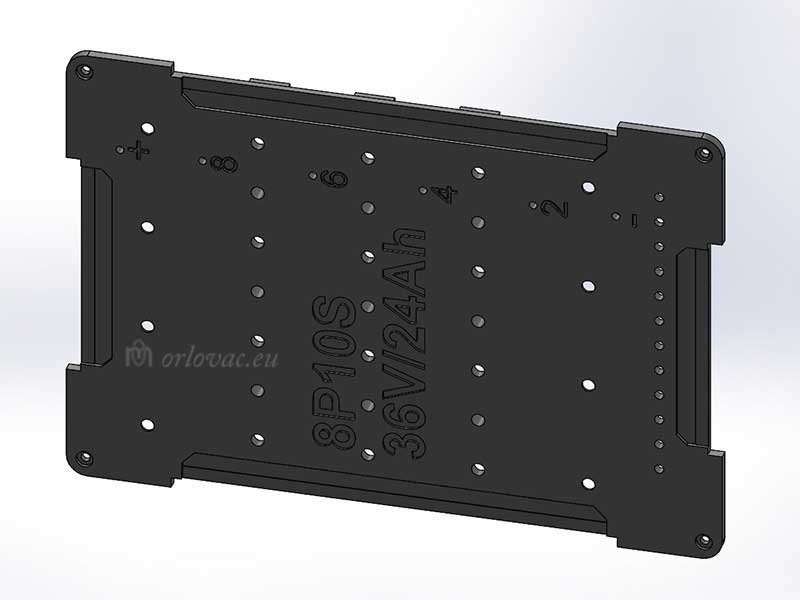
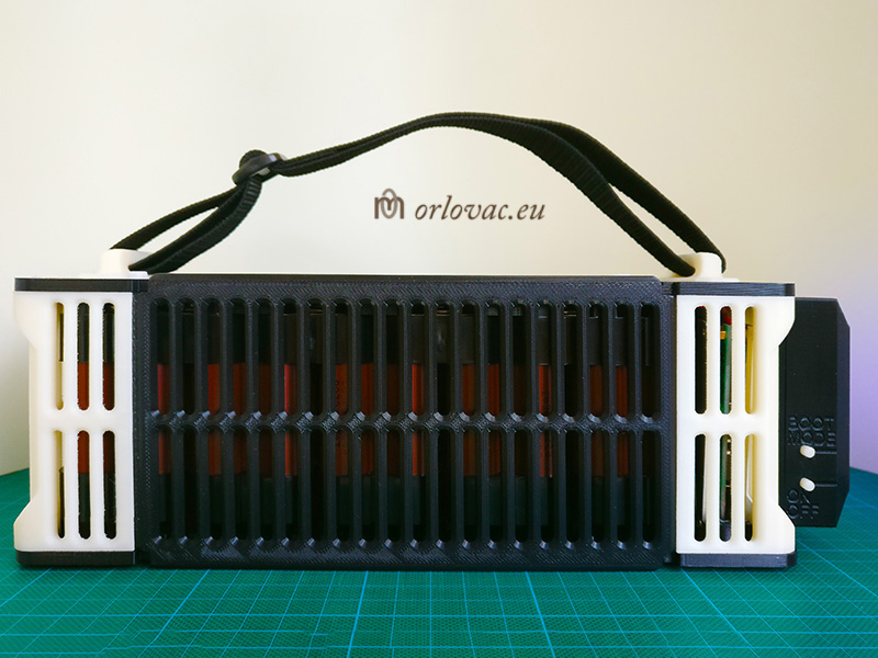
Above is image of competely build Li-Ion battery pack, 36V 24Ah.
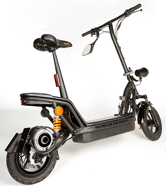
I have Tante Paula Maximillian II
an electric German scooter (1KW version, 2010), which is supplied by 36V (three lead-acid batteries 12V 12Ah).
I use this scooter only during my summer vacation (aprox 5-6 weeks per year). I used to use Panasonic AGM batteries, type:
LC RA1212PG-12V 12 Ah, but
I have these three batteries hard to survive for two seasons, they are heavy and capacity is quite low.
Always some of them are damaged or have lost capacity, when I need it,
despite my attempt to keep them trickle charged during unused period...
Available space for battery pack
The space in my scooter, for these batteries are limited to: 350x180x105 mm, where I have to place my new developed Li-Ion battery pack. I made several attempt to find appropriate battery package design solution. Here with super capacitors, but both of this designs are rejected.
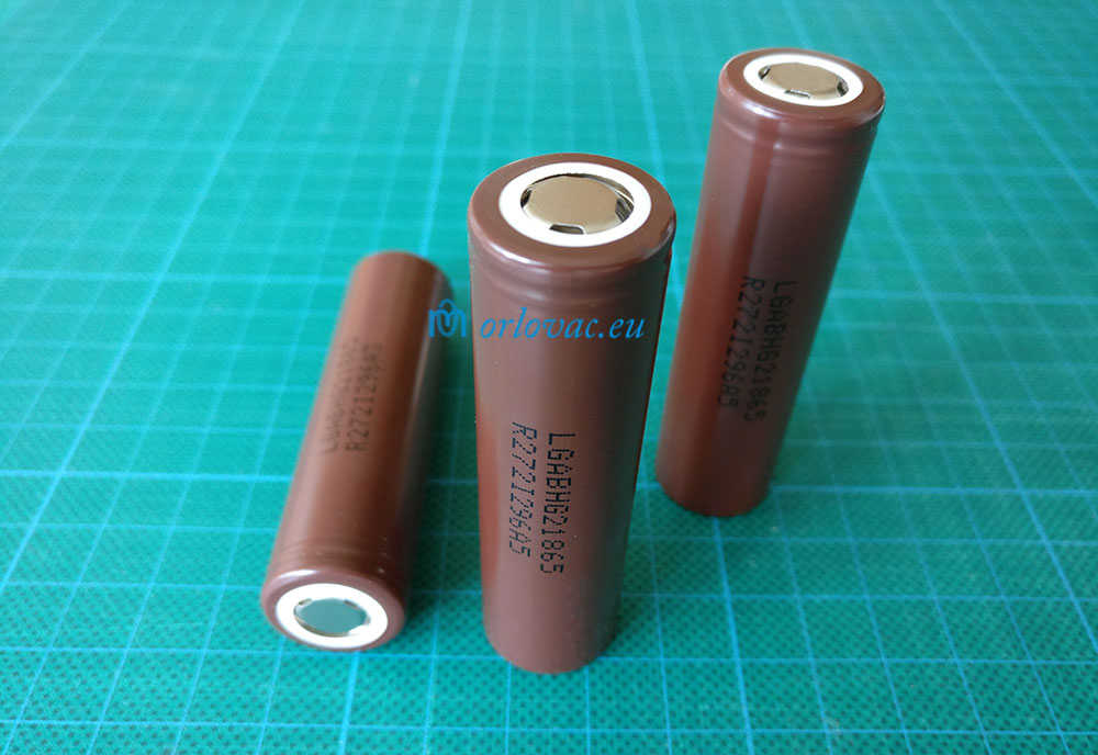
Battery Cells & BMS
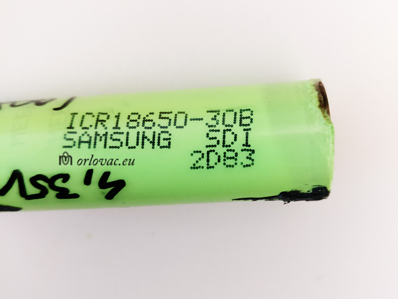
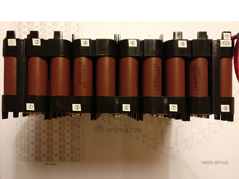
The question is, why not buy already built battery pack instead of building it myself? This was not an option for me. If I bought factory built battery pack, I do not know anything about quality and capacity of used Li-Ion cells. Build quality could also be compromised, with used thin buss bars, insufficient BMS (Battery Management System). On the last time the price of high capacity 18650 cells dropped significantly. I decide to buy LG cells: INR18650-HG2 3000mAh, 20A at NKON. To get even better price, I and two om my colleagues ordered 200 of these cells for EUR 3.45 per cell.
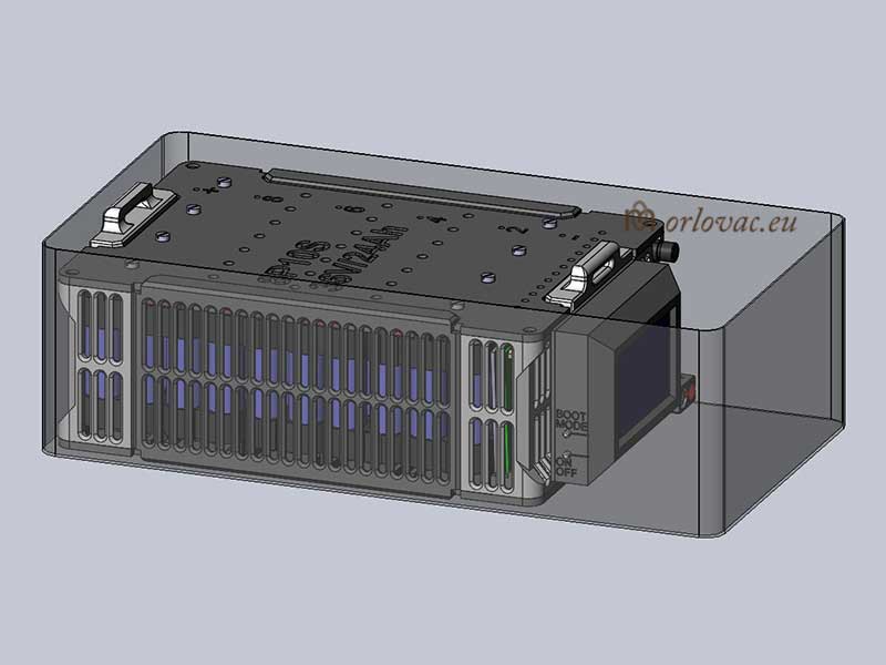
In the battery compartment there is place for 80 cells connected 8 in parallel to get 24 Ah and 10 in series to get desired voltage of 36V. The result is 80 cells in total.
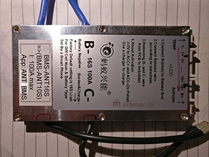
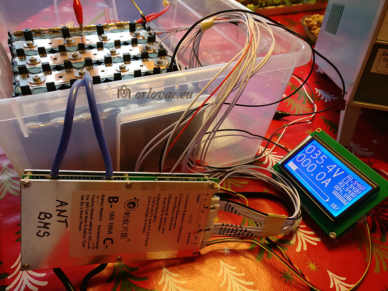
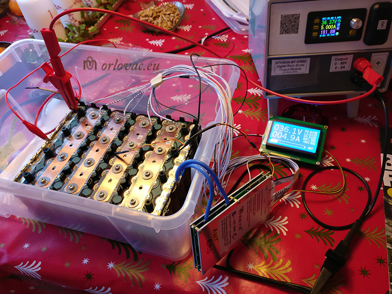
As I have to drive ~1KW electric motor of 36VDC nominal voltage, I need approximately 30A continuous current supply. When I accelerating, there is more demand, so I decided to allow as much as three times nominal current, i.e. 100A. Though, I chose 100A BMS, ANT-BMS with Blue Tooth from Aliexpress. I picked it up with Display too, because it was not expensive.
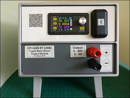
The Charger, DPH5005 Power Supply
Click on the image above to see photo album.
Before I started to build the battery pack I decided to build good controlled charger. As I have already good experience with RuiDeng Power Supplies
(one I built earlier, described above:
DPH3205) I ordered RuiDeng's
DPH5005,
50V 5A Power Supply with Blue Tooth and USB connection, which I build in a similar way.
Here is used the same enclosure, but different primary Power Supply to cover max 50V 5A output. I won't spend too much time to describe
this construction, because it is detailed described in previous article. Here you can find many picture, BOM and
Schematic Diagram, how I
built it. This decision gives me more freedom how I will charge my battery pack and at the same time I have a nice and practical
bench Power supply from 0-50V and 0-5A regulation. In this case I can always decide to charge battery pack at any usable voltage,
for example: 80% of capacity, i.e. 40V instead of full capacity of 24Ah (42V). For example, if i wish
I can charge it only to storage voltage of 38V...
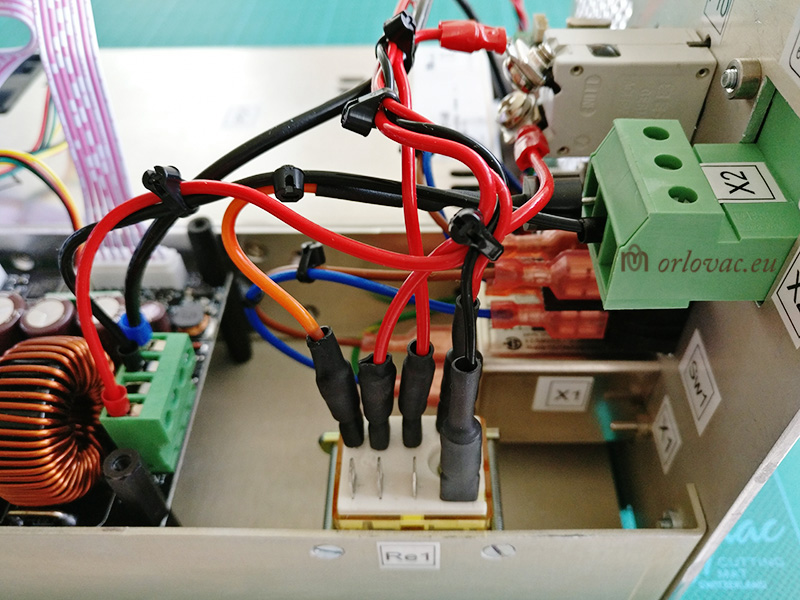
Bill of materials for this PS is very similar to above described DPH3205. The difference is, obviously, another output power control unit DPH5005 which I chose with BlueTooth and USB Connection. Bear in mind that you can't use BT and USB at the same time. You need another primary Power Supply to get 50V 5A at output terminals. I used Cosel PBA300F-48, 48VDC 7A. Re1, IDEC RH2B-U is fine. I did not have its socket, so I used fast-on 4,7mm (5 pcs) cable crimp terminals, covered with shrink sleeves. The relay is mechanically fitted onto chassis. I have built DPH5005 in a very similar way as DPH3205.
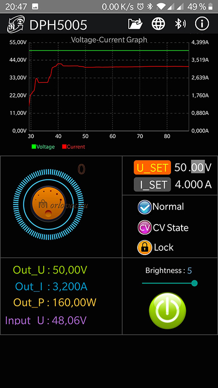
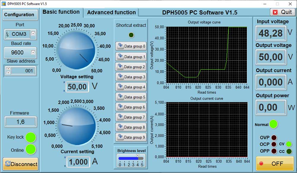
This PS is possible to control with Andorid app
DPH5005, provided free of charge as well as
DPH5005 PC software.
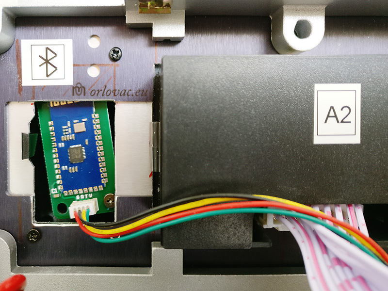
I have placed BT unit
outside of the box on the front plate, inside
a half of tiny plastic enclosure.
USB interface
is placed on the rear plate of the PS unit. Because it is only a single communication connector on the DPH5005 board,
you can connect only one of them at a time. If USB interface is used, com cable need to be moved from BT to USB unit.
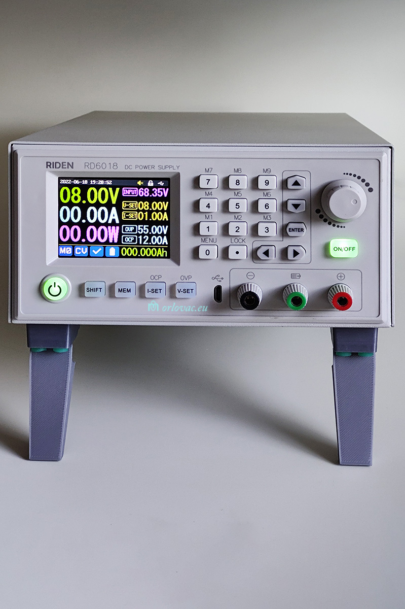
For your information: just after I built this PS, RuiDeng released this fantastic
RD6006W,
60V 6A Power Supply with a useful enclosure.
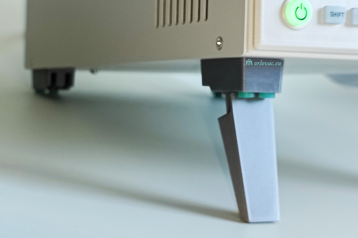
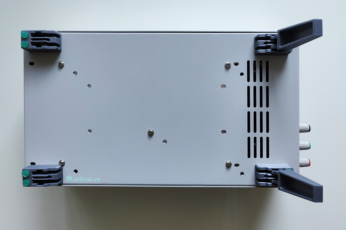
Now you can download and 3D print
my tilt feet on Printables for these Power Suypplies, usefull for all RD60xx models. Here
is my RD6018W assembled with my designed and printed
tilt feet and mounted on
a PS enclosure.
MOT
Click on the image to see photo album.
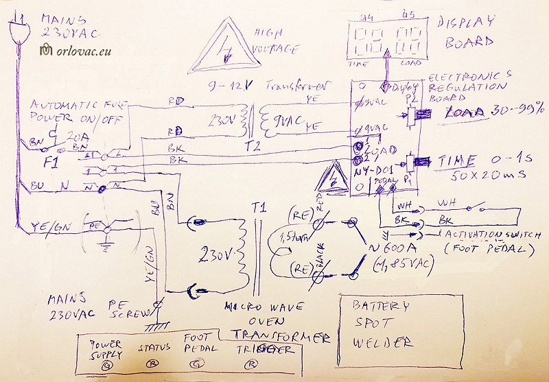
MOT: Microwave Oven Transformer battery spot welder. It is intended to use as a cheap battery, buss bars welding device.
I spent lot of time in building and testing of
this welder and realized that it is not enough good and reliable for use. Believe me, it is quite bad with unreliable welding results. I will show
here some picture from my build and schematic diagram, but I gave up. Do not use it for any serious work! May be used as a RSU: Resistance
Soldering Unit only. As I mentioned, welding result are poor
with too much thermal stress on the cells, which I could not accept. I almost
finished building this unit before I assumed that it is not for me. The display is supposed to be placed on upper part of this unit.
The schematic diagram is created as hand sketch only.
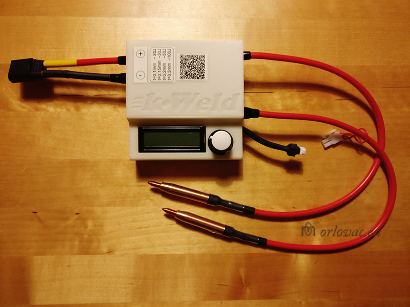
kWeld Battery Spot Welder
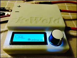
Click on the image to see photo album.
I decided to buy currently best available battery spot welding device on the market from Germany at
Keenlab.
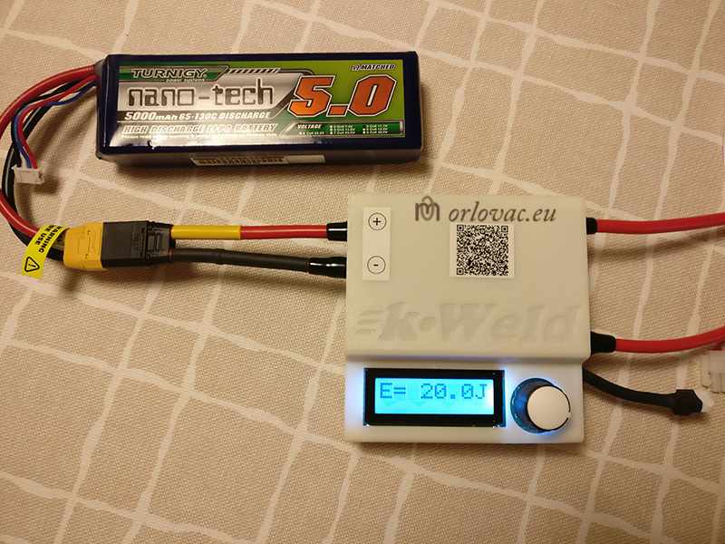
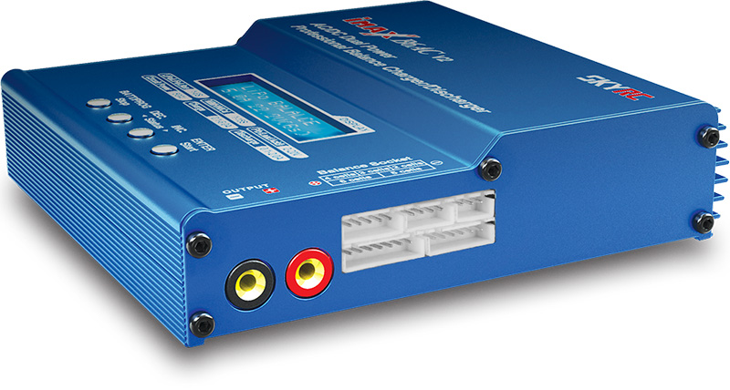
I bought a recommended Li-polymer Tornigy
5Ah battery for this device and SKYRC B6AC V2
Charger with balancing function.
The Battery is enough powerful with incredibly energy level which can deliver up to 130C of discharge current. In the short welding
period, it can provide up to 2000A (2KA) of current, without battery damage. It make possible to
weld the whole battery package (4 weld per battery times 80 batteries =320 welding spot) with only one charge.
This device uses predefined energy level i J [Joules] to perform welding connection. More information is on
Keenlab.
The welding points are completely controlled with a predefined energy level and a detailed quality feedback after every welding exercise.
Keenlab does provide a STL file to make 3D printed enclosure, free of charge. You have to assemble everything yourself and a very good instructions
are provided.
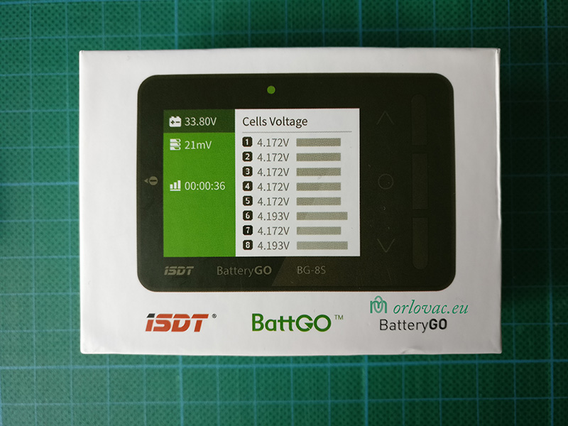
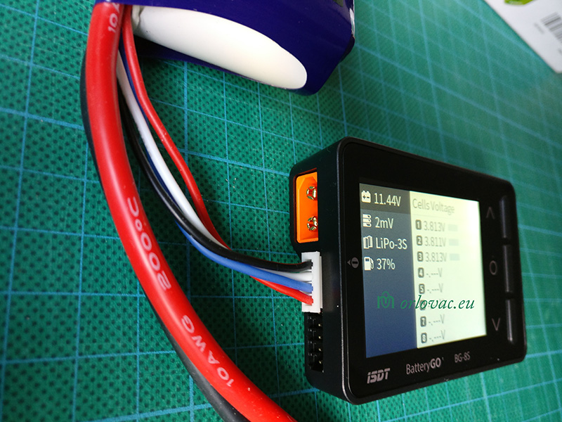
You do not have to buy dedicated charger for this battery as I did. You can buy much cheaper balancing device, for example ISDT BG-8S. Charge the Turnigy battery with ordinary bench charger up to 3x4,2V and perform only balancing with this unit, by connecting only battery balancing connector.
The Battery Package
Click on the image above to see photo album.
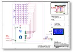
I create the Schematic Diagram of this package,
as well as detailed drawing showing the building process.
BOM
| Part | Description | Manuf. |
| 01. | 18650 Battery Copper Strip Hight Power, thickness of 0,3mm. | ANNPower store, Aliexpress |
| 02. | 18650 Battery pure nickel belt 5P with 21mm cell spacing, thickness 0,2mm. | - || - |
| 03. | 18650 Battery pure nickel belt 3P with 21mm cell spacing, thickness 0,2mm. | - || - |
| 04. | Pure nickel bus bar, thickness 0,2mm, for Plus & Minus battery end terminals. | - || - |
| 05. | 18650 hight quality Battery holder for big power, size 6P, support bar included. | - || - |
| 06. | 18650 hight quality Battery holder for big power, size 4P, support bar included. | - || - |
| 07. | 100 pcs 18650 Battery insulation, only for battery Plus Terminal to prevent short circuit. | IC GOGOGO store, Aliexpress |
| 08. | Smart 7S0S Li-Ion ANT BMS, 100A with LCD. Display included, two temperature sensors NTC 10K and all connection wires. You will get ANT- or MY-BMS app as well. User manual is included but english is very poor. For example: Pressure means Voltage... | - || - |
| 09. | XT150 original Amass 150A connector kit. Red and Black connector holder with socket and pins. | Aliexpress or eBay |
| 10. | Screw M4x8-12mm, any kind. | Any brand |
| 11. | Washer, for example: SRKB 4.3x15x1 ID4,3mm; OD15mm x 1mm or similar. | - || - |
| 12. | Polyamide or nylon spacers M4x10mm 8pcs, like PA6.6 DSN M4080x10. Only for upper part to compensate for cut off battery holder's tabs. | - || - |
| 13. | Some kind of plate screws, for example: RXS 3.5x13 FZB OD3,5mm x 13mm, 10pcs (4 for upper part, 4 for bottom part and 2 for XT150 connector) | - || - |
| 14. | Some kind of plate screws, for example: RXS ST2.9x9.5 FZB OD2.9mm x 9mm, 4 pcs for Display Box | - || - |
| 15. | Copper insulated wire, 6mm2 (AWG10). You need less than 1m of black for "Minus terminal" and red colour for "Plus terminal". I have used wire with PTFE (Teflon) insulation. (One mm2 is enough for 13,5A current through it. | - || - |
| 16. | Some kind of nylon belt 25 mm wide, about 600 mm long with appropriate metal or plastic buckle to make a handle. | - || - |
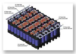
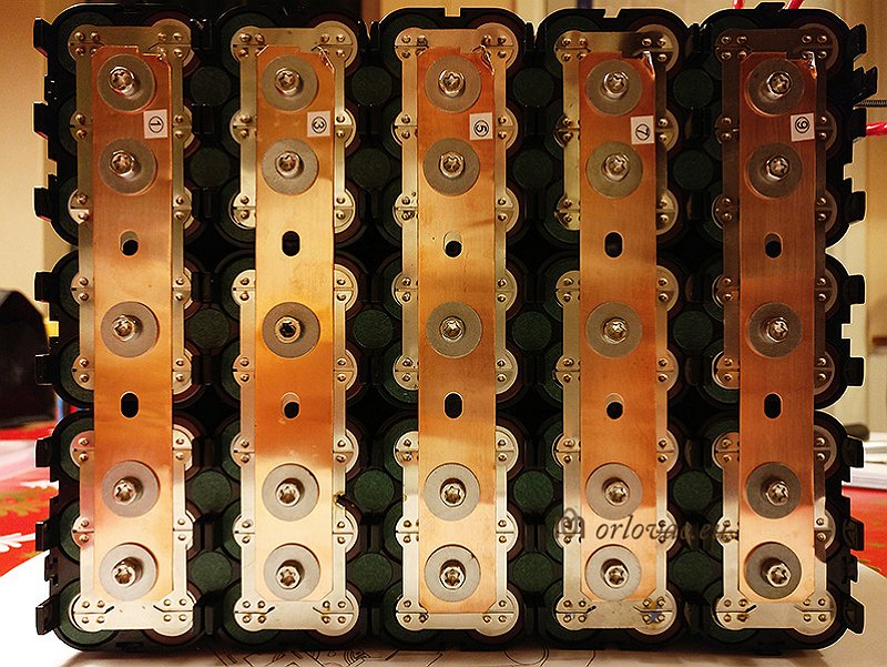
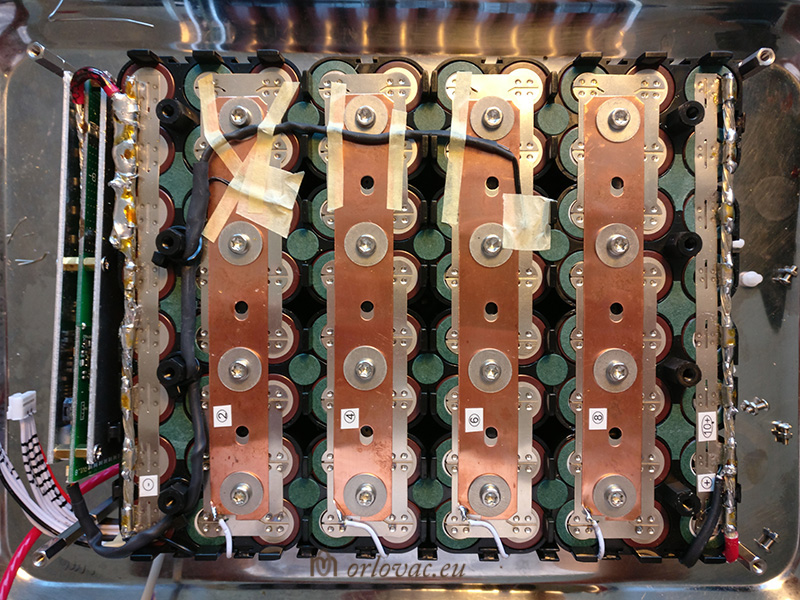
ANNPower has the best 18650 li-ion battery holder I could find. The holders are very sturdy together with nickel buss bars and
copper belt. This combination ensures best combination to minimize power dissipation on battery buss bars.
Nothing, commercially available is not near as good to this fantastic, but not cheap solution.
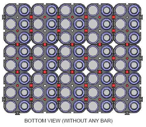
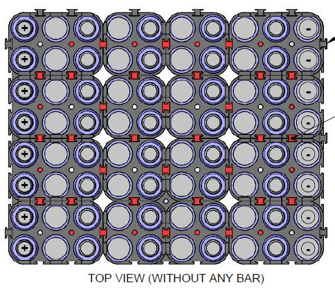
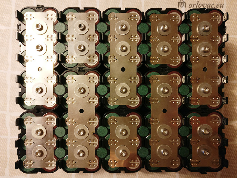
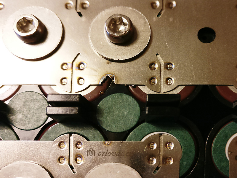
 Here we have one problem though. This holders are designed for parallel connection of big power packs only.
So far everything is nice
(shown on bottom part of battery pack holder connections),
when we need to make serial connection of a battery pack
(top part),
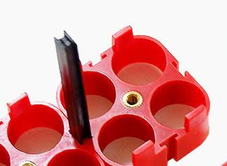
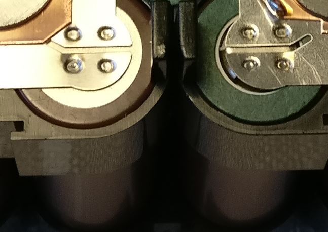
we run into problem. The holder tabs make it impossible to mount
nickel bus bars. I have to find some solution for this inconvenience and I solved this problem by rotating upper battery
holders in serial direction. At the same time I have to remove some battery holder tabs
(marked on this drawing) to make possible to fit buss bars.
This placement gives me several M4 holes, enough to make a safe and reliable connection. I placed nylon stand-offs M4x10 mm
to replace missing holder tabs in which I fit
nylon
screws through battery lid
(top part).
Here we have one problem though. This holders are designed for parallel connection of big power packs only.
So far everything is nice
(shown on bottom part of battery pack holder connections),
when we need to make serial connection of a battery pack
(top part),
we run into problem. The holder tabs make it impossible to mount
nickel bus bars. I have to find some solution for this inconvenience and I solved this problem by rotating upper battery
holders in serial direction. At the same time I have to remove some battery holder tabs
(marked on this drawing) to make possible to fit buss bars.
This placement gives me several M4 holes, enough to make a safe and reliable connection. I placed nylon stand-offs M4x10 mm
to replace missing holder tabs in which I fit
nylon
screws through battery lid
(top part).
- The bottom part battery holders orientation:
For 8 cells in parallel direction, we need: 2x3 + 2x3 + a 2x2 holders (8 cells in parallel). We need five times this combination to cover
complete bottom part of battery pack. This orientation is normal layout for what this ANNPower holders are designed for.
- The top part battery holders orientation:
battery holder are orientated in serial direction instead. I used this layout: 2x3 + 2x2 + 2x2 + 2x3. I need four times
this combination to cover top part of battery packs (10 parallel rows in serial connection).
When top and bottom battery holders are arranged in this way, all plastic support
link bars can not be used as supposed. Those of original
length are used 14 pcs. For the rest I used cut pieces only.
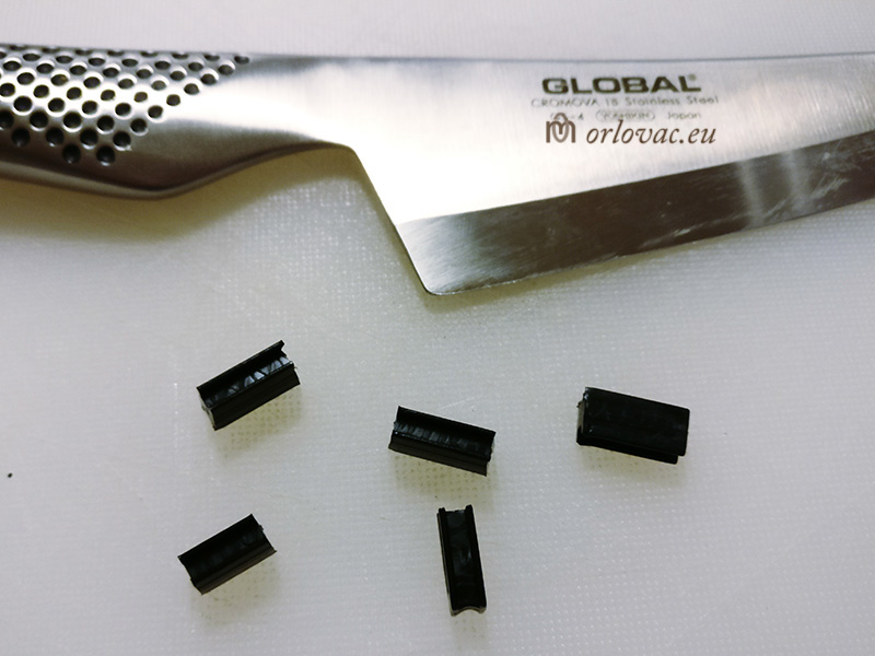
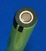
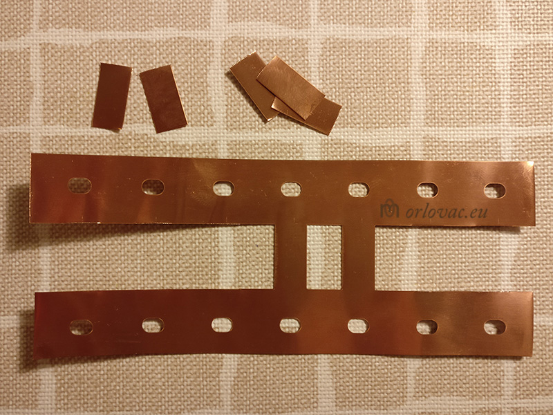
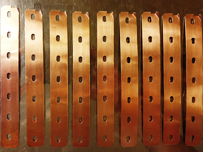
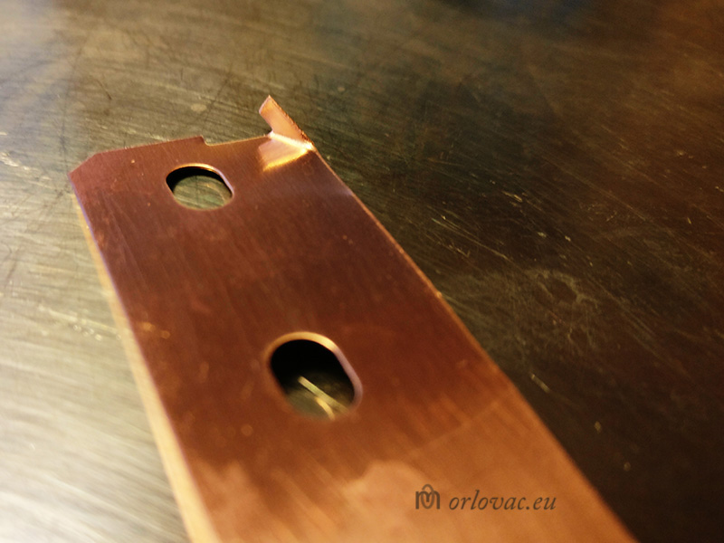
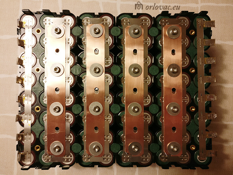
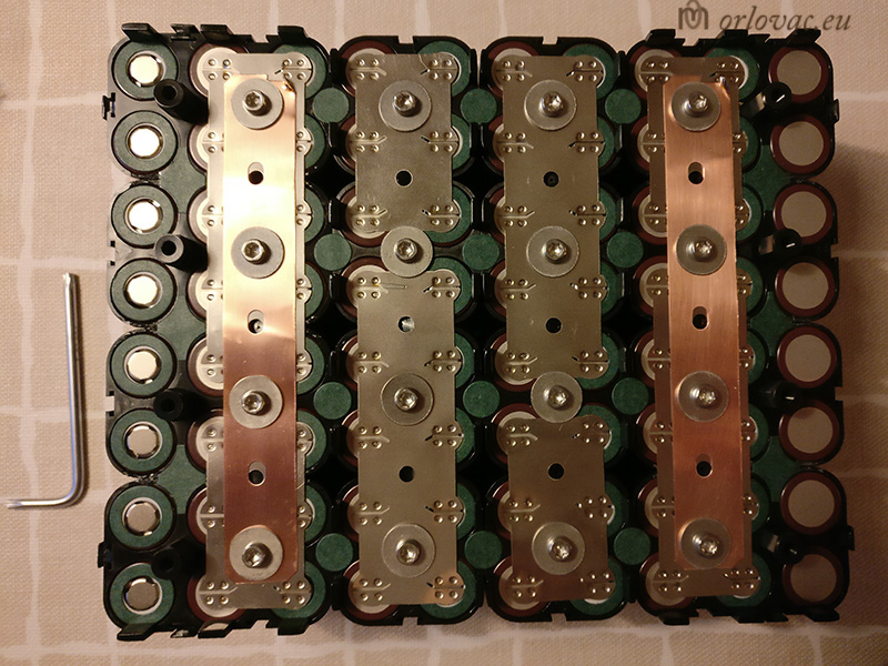
Prior to any welding of bus bars I placed an insulation on a '+' part of every cell to prevent possible short circuit. Next step is to mount all bus bars temporarily, fixed on place by help of screws to make possible spot welding them on both sides of the batteries. When welding process is completed, screw need to be removed for copper belt placement. The Copper belt has shape of letter 'H'. I made cut, separating them in separate 'I' shaped belts. On each of them I made a notch, preparing a soldering tab for BMS sense connections. All copper belts are mounted onto battery holders, by help of M4 screws and washers.
Bear in mind, when working on the battery pack, there is always risk to make unwanted short circuit! As I mentioned earlier, you are playing with lot of energy. You can imagine my surprise when I dropped an non insulated torx key. Use insulated tools only!
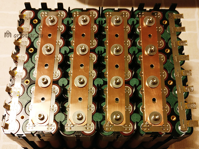
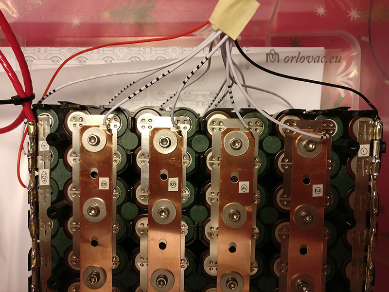
For end Plus (+) and Minus (-) connection, I used pure nickel belt of 'H' shape, 0,2mm thickness and 20,2mm cell spacing. I cut them to get 'E'
shape, pre-soldered and
then welded on end Plus and Minus
poles of the battery pack. I place copper stripped wire across whole length of each parallel battery pole. 'E' belt fingers are
used to make tight grip round non isolated part of copper wire and finally
soldered them together.
It is important to use a powerful soldering iron to done soldering quickly (50W is quite weak, use something between 100W-200W.
Reason is that we want transfer as little as possible of heat to the cells.
In this way I made reinforcement
to support high current flow and at the same time minimize heat dissipation with this connection.
Prior to temporarily solder all BMS' sense wires for system test, I made
serial
connection labeling.
BMS' sense
wires are soldered onto copper tabs, according to the
schematic diagram.
When first time connecting the BMS, it must be done in correct way:
1) Connect BMS' "B-" on battery "-" terminal first!
2) then connect the BMS connectors P1 and then P2.
When disconnecting, do it in reverse order!
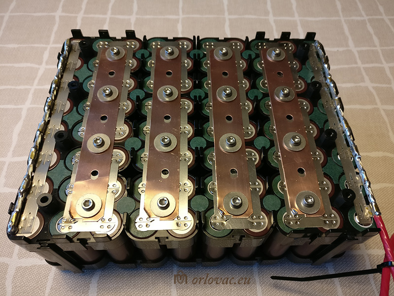
The built system is tested and everything went well at the first attempt. It is fascinating how nice everything is working despite so poor Chinese documentation. Now is time for a nice arrangement of all sense wires, which I fed through my own drilled holes in the plastic support link bars. Two temperature sensors T1 and T2 are laid over copper bars numbered 2 and 6.
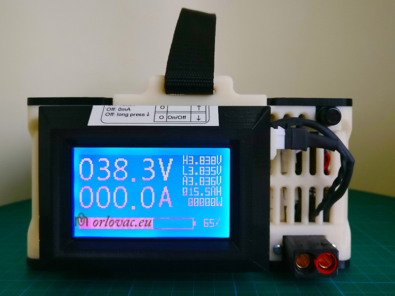
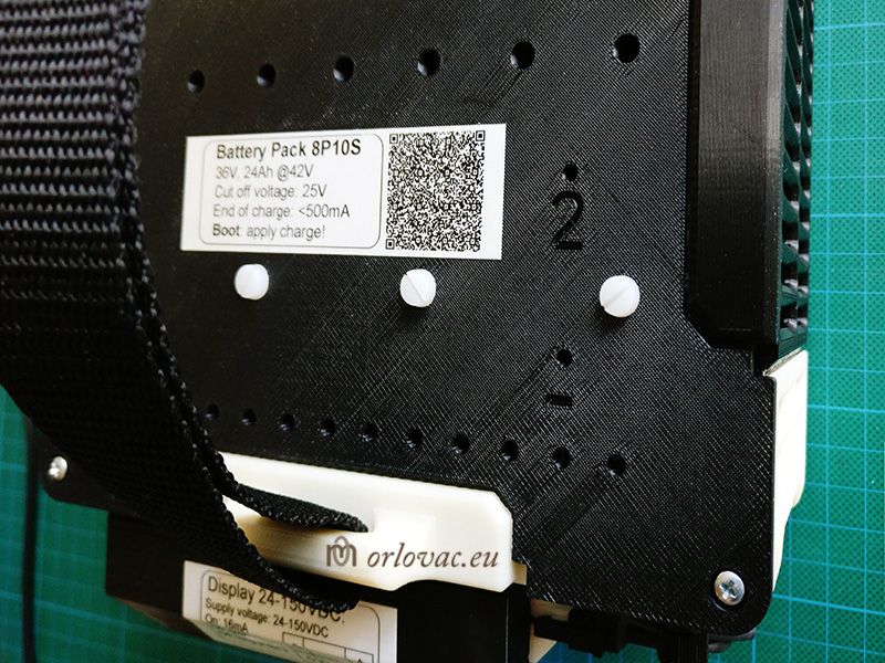
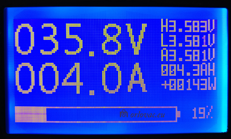
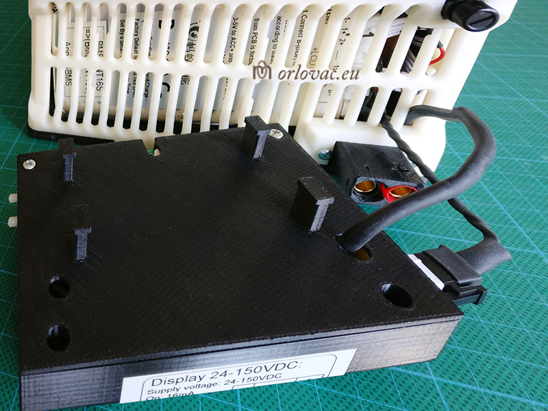
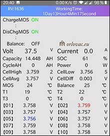
The Battery Display and BMS
The Battery display
is monitoring the whole system and provides Blue Tooth connection to Android or iOS app.
When enabled, display current consumption is about 16mA. When disabled it draws 0mA!
Enabled display does boot the BMS through communication cable. The connection of BMS and display are
shown on the schematic diagram.
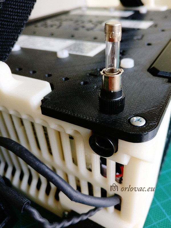
I put a fuse F1 (250mA) in plus display supply line. Display minus supply connection can be fitted
on the battery Minus or output Minus terminal (BMS: C-). I chose the second one, because to protect
the expensive battery pack to be possibly drained below the cut-off battery voltage (2,6V/cell) and prevent possible
battery damage over a long time.
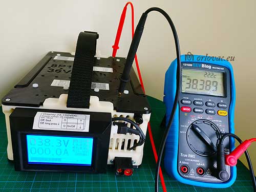
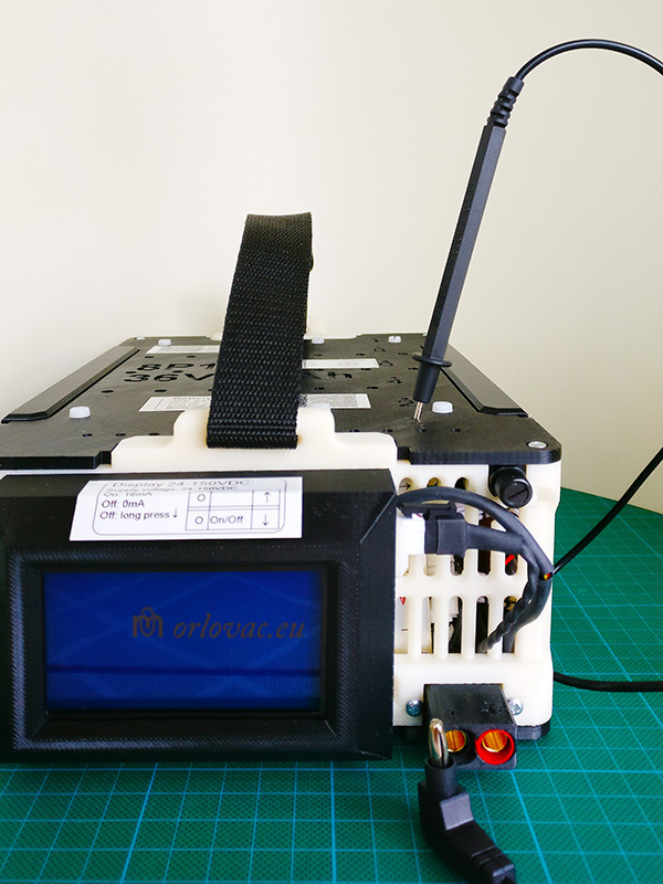
Here are two ways to boot the BMS:
- simply apply the charge voltage to battery XT150 output connector, or
- use a bit of wire or multimeter measuring
probe
and make short circuit between battery Minus and output Minus terminal to
feed supply voltage to the display.
The BMS has to be booted, only if it is shut down.
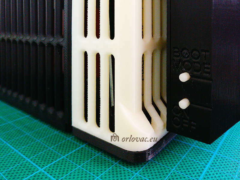
To turn Display on and off: long press on 'On/Off'
button (lower one)
or use app. To browse the display menu, press: UP or DOWN
button.
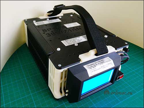
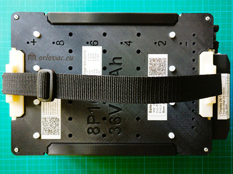
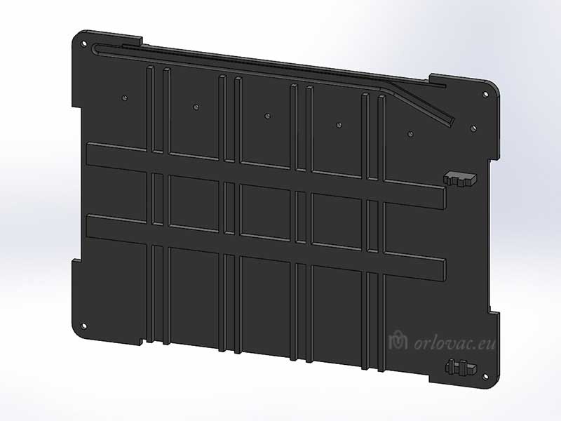
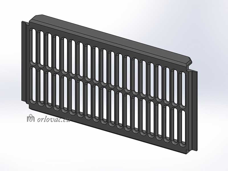
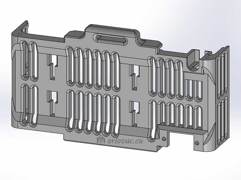
The Battery Enclosure
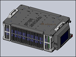
Click on the image to see photo album.
When the package is built and tested, I decided to design my own 3D enclosure, which I printed on a 3D printer.
If it is of any interest, I have placed all STL files (free of charge) needed to get this project printed:
battery box,
display box and
XT150 connector holder.
The enclosure is made of: one top and
bottom part: two identical
side parts with ventilation openings;
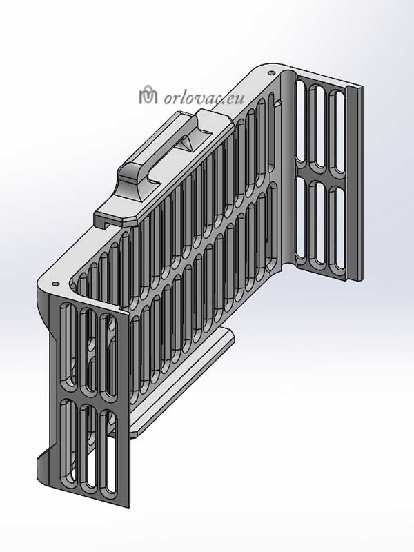
one gable part with ventilation
holes and one gable
where I integrated Display box holder,
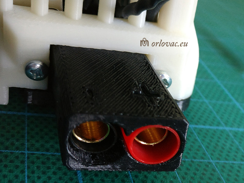
the Fuse holder for Display and
holder for XT150,
original 150A Amass output connector.
All part are designed so that they keep itself together and finally four plate screws through upper box part and
four through bottom box part are holding everything tight together.
I used a bit of nylon belt 25 mm wide,
to make a practical handle.
Android & iOS Apps
 |
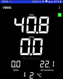 |
 VBMS App.
Click on the image above to see photo album with lot of possible adjustments. VBMS App.
Click on the image above to see photo album with lot of possible adjustments. |
Because above described ANT-BMS has built-in Blue Tooth it is possible to monitor and control this BMS with two Andorid apps and an iOS App.
Android app provided with the BMS is free of charge and is named MY-BMS, which can't be found on Google Play. The second one,
VMBS can be found on Play store
and is developed by company Vortecks, with price tag of EUR 6.5.
iPhone users does have an iOS app named ANT BMS, free of charge on
Appstore, which seems to be much better designed.
There is a tons of parameter adjustments in apps. The most of them are self explanatory, some are not. VBMS app provides you with an instruction guide. You have to adjust 'Number of cells' (in my case: 10) to get correct voltage reading for every parallel row. I limited 'Balance current' to 100mA, because not to destroy balancing transistors. If you get wrong current reading from battery display and app, you have to adjust 'Current Sensor Range' or 'Maximum Output Current' until you get correct reading. Play with this value. I am showing here in my photo albums: MY-BMS and VBMS adjustments.
Click on the image above to see photo album.
The weight of the complete battery package is
5.4 kg compare to 12kg of original lead acid batteries weight.
Practical tip: to save battery life, charge it to 80% (40V), like Tesla do with its car batteries,
or 90% (41V) instead of full capacity (42V). At the same time, adjust in the BMS
lowest voltage warning, for example to 32V.
If you have some comment or suggestions, feel free to send me a message.
Designed and built by: Marinko Orlovac, 2019.
Reviewed by: Tomas J Carlsson
Dustbuster Flexi, battery replacement
Updated: April 10, 2020.
Before all: Lithium-ion Safety Concerns:
If you do not know what your are doing or you do not have any experience
about these batteries, do not play with them. They can store lot of energy, which can hurt you seriously
and you can burn down your home. I have warned you and I won't be responsible for what you are doing.
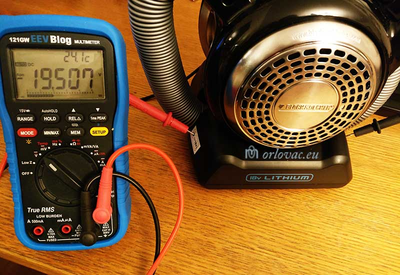
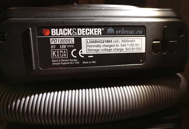
Six years ago I purchased Black & Decker portable vacuum cleaner model: PD1820LF 18V Lithium-Ion Dustbuster Flexi. Best portable vacuum cleaner of that time for my car. It is very well designed with powerful (quite loudy) DC motor.

Click on the image to see photo album.
Problem: this device works as fine as when I purchased it, but there is one annoing problem, which is battery capacity.
With included battery pack I could never vacuum clean whole my car with one battery charge. If I finished cleaning passenger compartment,
the battery was completely flat and I must charge it to continue cleaning car's boot. The charge takes several hours and I have to clean my car
two times to get it clean.
I checked web for battery replacement for this model, but could not find any information at the moment of doing this project.
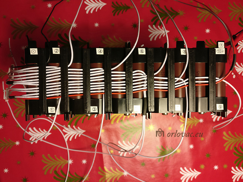
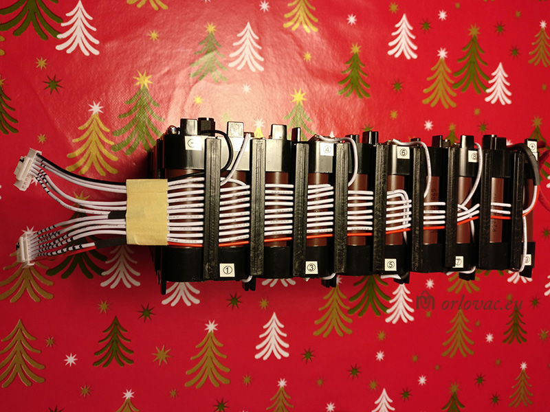
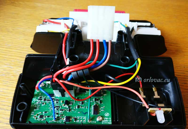
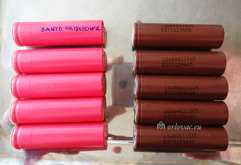
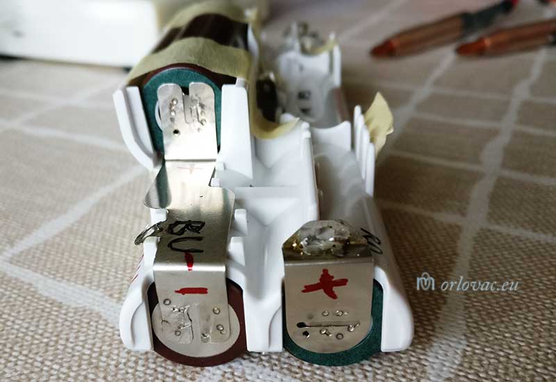
When I take appart cleaner's battery compartment,
it revield 5 pcs Sanyo batteries UR18650W2 of 1500mAh capacity. As I already have powerful spares of
LG HG2 Li-ion batteries 3000mAh
(mentioned earlier on this site), I decided to replace original batteries with these LG's I already have.
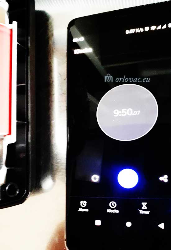
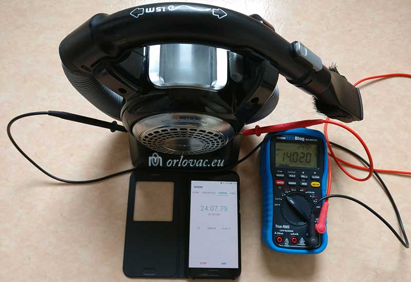
Before I started with reconstruction of this battery pack, I measured vacuum cleaner's working
time with fully charged batteries, which was less than
10 minutes.
Decision was easy because I owned kWeld battery tab spot
welder tool, described above on this site too.
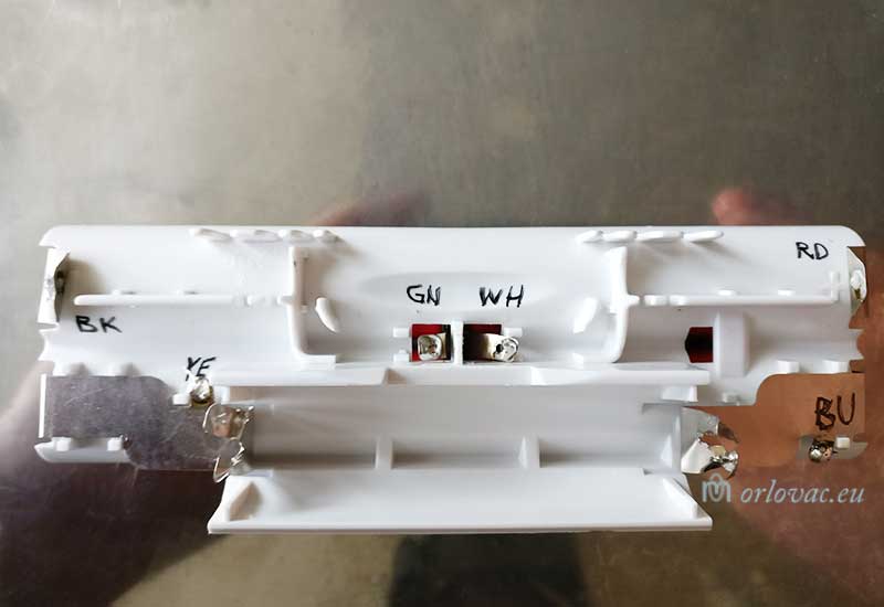
I made a note about wire
colour before desoldered them from the battery
holder:
 plus (+): RD
CT1: WH
CT2: BU
CT3: YE
CT4: GN
minus (-): BK
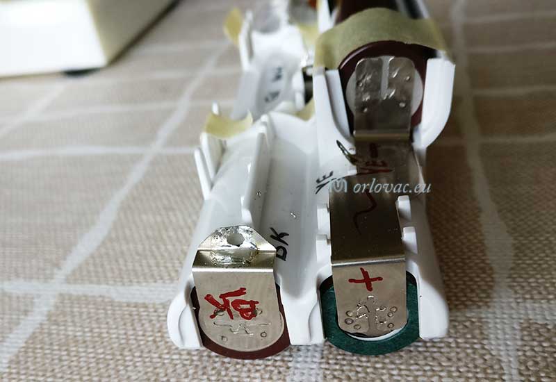
When I separated and extracted old batteries, I intended to keep original battery nickel tabs to reuse it. I succeeded quite well, reused them and welded on new batteries. After first charge of new batteries, working time is tested. The benefit is obvious: now I have about 24 minutes time to clean before need to charge batteries, which is more than I need. The problem is now successfully solved. If this description helps someone, I'll be very glad.
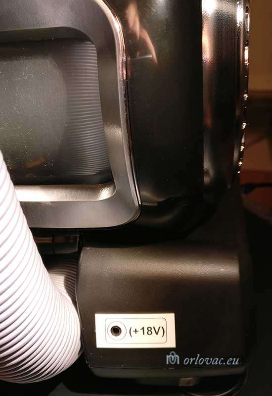
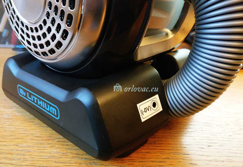
At the same time I added a tiny improvement: two
holes on battery
compartment to make possible
to check battery voltage, without to
open it. A new label is added to show new useful information.
Created by: Marinko Orlovac, 2020
Temperature Calibrator
Click on the image to see photo album.
I always wish to build some kind of temperature calibrator, so that I can test and verify some of my
different thermometers or temperature probes.
I came across an interesting article in an excellent Australian electronics magazine named Silicon Chip.
In the January issue of 2020, on pages 92 - 95, is a description of a practical
Thermometer calibrator.
To get whole article, this issue need to be ordered from Silicon Chip, or try to find it in your city library.
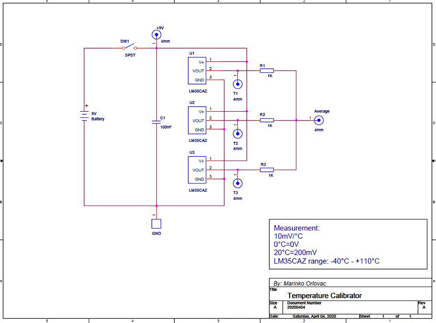
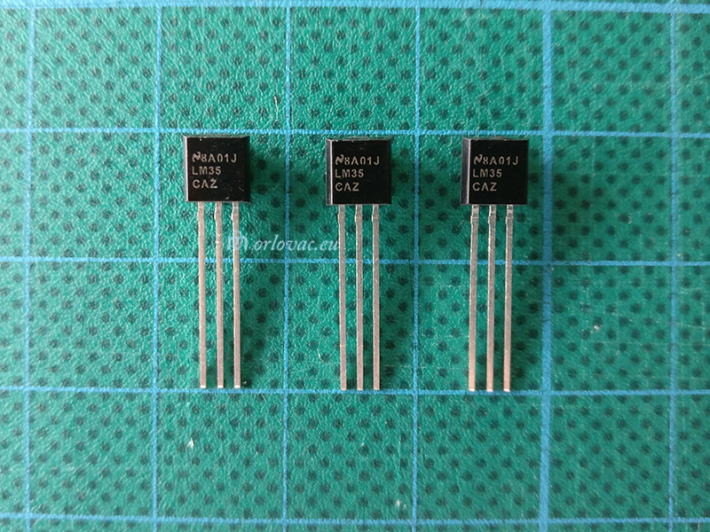
Here are used three LM35CAZ Precision Centigrade Temperature Sensors in TO-92 package.
LM35CA is more accurate, with greater range of temperature measurement (-40℃ - 110℃)
and more expensive than model LM35. I ordered them on ebay from
Kessler
Electronic in Germany, to avoid cheap Chinese counterfeits.
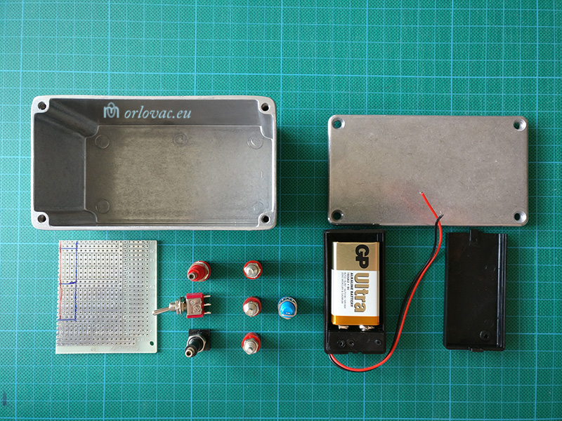
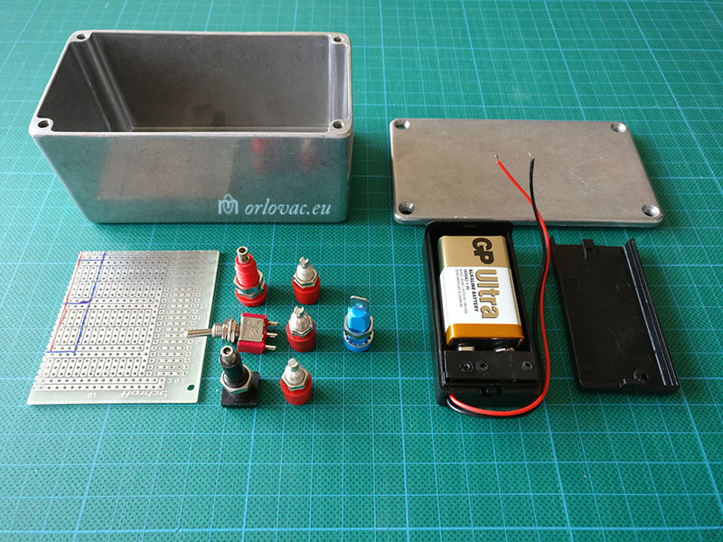
The BOM of materials can be seen on pictures:
01,
02,
03,
04, and
05.
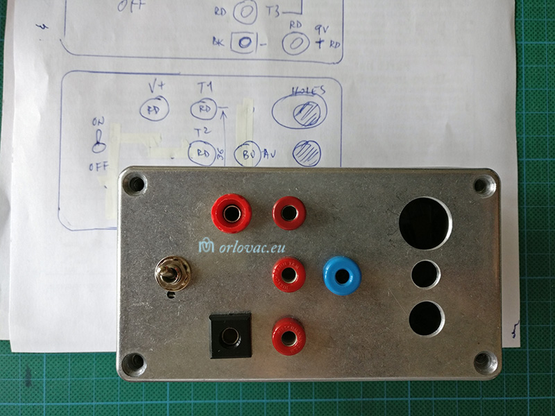
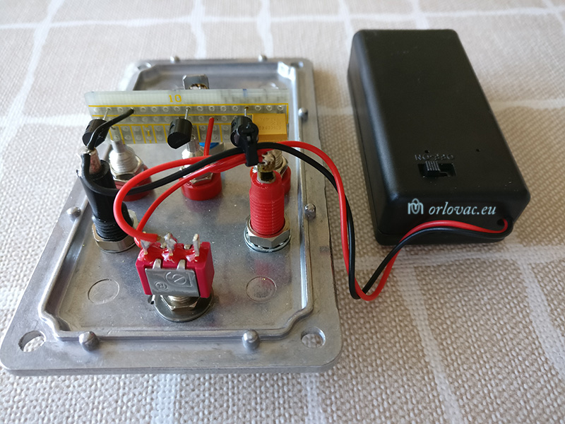
Aluminum diecast enclosure 116x65x55mm or similar
(Hammond Electronics)
is used for housing of sensors and as a stable temperature measurement environment with low
temperature gradient. Three different
empty holes on the lid of the box are places where testing thermometers
or sensors have to be placed for temeprature check and comparation.
LM35CAZ could be supplied from 4V to 30V, therefore I used
Standard 9V battery (6LF22) and I had a battery compartment or you can use
ordinary 9V battery snap connector. An SPST switch for power on and off is used.
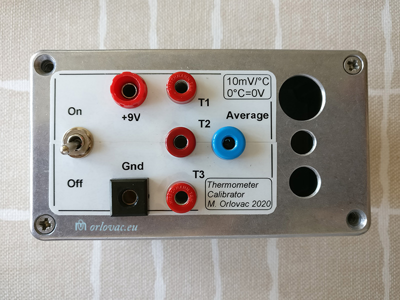
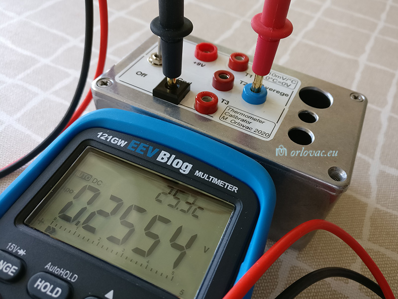
I used DIA 4mm "banana" sockets of different colours as measurement terminals.
One black for GND; red for T1, T2, T3 and battery voltage check. A blue one for 'Average' temperature measurement.
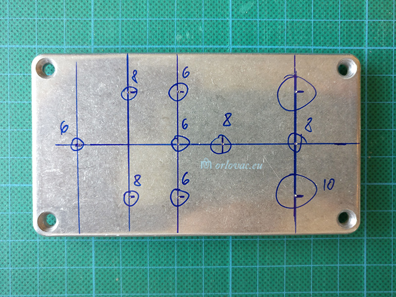
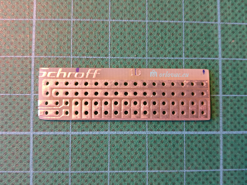
A piece of a universal soldering board
to solder temperature sensors, which is cut and filed to shown
shape.
3 pcs 1K resistors 1% 0.1W connected as it is shown on the
schematic diagram to
get average output voltage for sensors T1, T2 & T3. Average=(T1+T2+T3)/3 [mV].
MY IMPROVEMENTS:
I have added two extra banana socket
terminals:
one red for battery voltage check (+9V) and a blue 'Average' terminal
to measure average voltage (temperature) from all three temperature sensors outputs, just to skip
manual output readout calculations. I placed three 1K resistors, but you can choose: 10Ω or 100Ω as well.
It is important to have here as low percentage value as possible for these three resistors (1% or better).
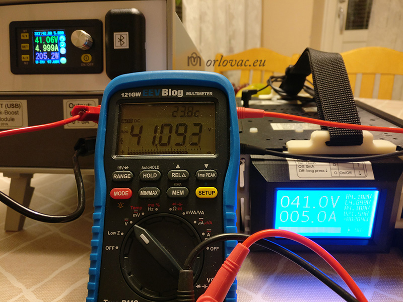
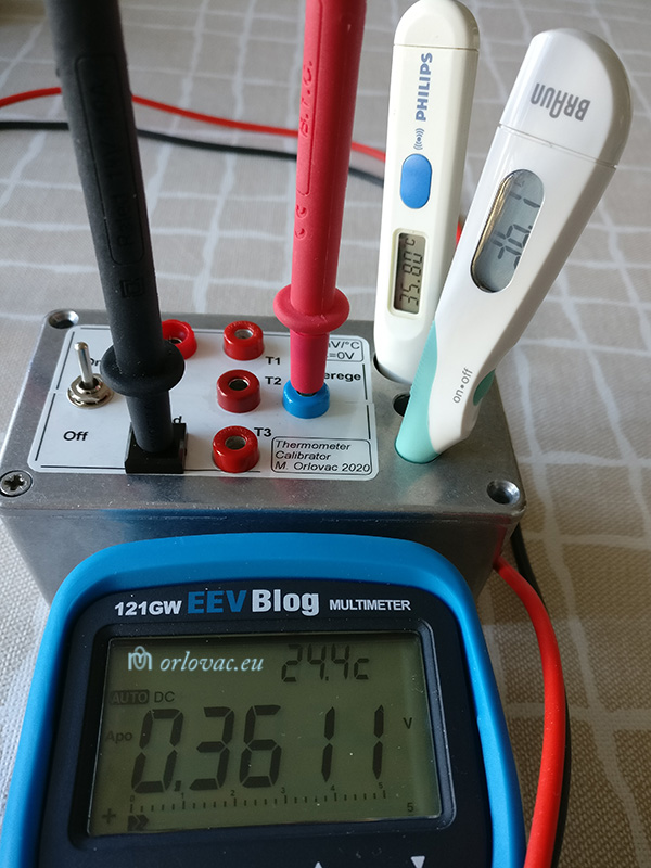
MEASUREMENTS:
The GIF
animation shows possible measurements on this unit. According to the datasheet, LM35's output shows temperature
in this way: 10mV/℃. For example: 0℃=0mV; 20℃=200mV; 100℃=1000mV=1V, etc.
NOTE: I did not connect LM35
sensors
thermally to enclosure by help of temperature conductive adhesive, as original
article suggests. It will be low gradient between temperature of sensors and air in the enclosure anyway.
If I suddenly change measurement environment, I have to keep this device for some minute to be tempered before
temperature measurement.
I have a proof of evidence for accuracy of this device. Look at
this picture,
where I am testing body
thermometers of Philips (20 years old) and Braun (new purchased).
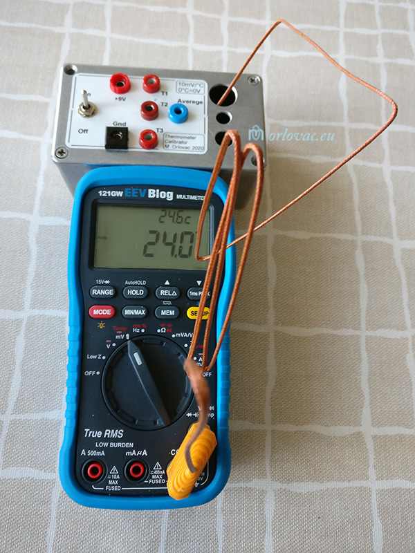
My multymeter model 121GW has built in a temperature sensor for rough ambient temperature measurement,
which can be seen on the top of the mulitmeter's
display,
or temperature may be measured by help of an
external probe too.
By: Marinko Orlovac, 2020
My own design for 3D printing

This year (2021.) I became a happy owner of an excellent 3D printer of Pruša brand. As my profession is 3D design,
I used that knowledge to create my own gadgets. As things are already created, and printed by me, I think
it could be interesting to share with others. Therefore, I have publised all finished design, under alias
Marin, on
Printables comunity.
If you already have or have a plan to buy a 3D printer, visit my part on Printables (former Prusa Printers), to see if
something interesting does exist. I have started qute a lot of new design, which are not finished yet to be
publised, but some will be soon. For some of my already publised design, I have been asked if I
could print something. But to print something, one must first to design the printed objects.
Often it is question of simple improvements of some existing products...
I do not mind if something will be big success or not. If I have something to share with me, I used to publish it.
Reason is that it could be of some help to somebody else.
All my design are free of charge to download and are test printed prior publication.
You may download, like or comment.
See you on Printables.